Built-in rotary cathode structure

A technology of rotating cathode and cathode, applied in the field of magnetron sputtering, can solve the problems of unfavorable large-area continuous production, poor universality of cathode gate structure, etc., achieve long-term stable sputtering work, reasonable design of water inlet and outlet, and improved uniformity sexual effect

Active Publication Date: 2017-08-18
武汉玖亿智能科技有限公司
View PDF6 Cites 3 Cited by
  • Summary
  • Abstract
  • Description
  • Claims
  • Application Information

AI Technical Summary

Problems solved by technology

[0003] The purpose of the present invention is to provide a built-in rotating cathode structure, the length of the magnetic pole piece can be increased according to the process, the cathode gate structure has good versatility, high target utilization rate and strong process stability, which is conducive to large-area continuous production. In the above background technology, it is proposed that the cathode gate structure has poor versatility and is not conducive to large-area continuous production.

Method used


Image

  • Built-in rotary cathode structure

Examples


Embodiment Construction

[0014] The following will clearly and completely describe the technical solutions in the embodiments of the present invention with reference to the accompanying drawings in the embodiments of the present invention. Obviously, the described embodiments are only some, not all, embodiments of the present invention. Based on the embodiments of the present invention, all other embodiments obtained by persons of ordinary skill in the art without making creative efforts belong to the protection scope of the present invention.

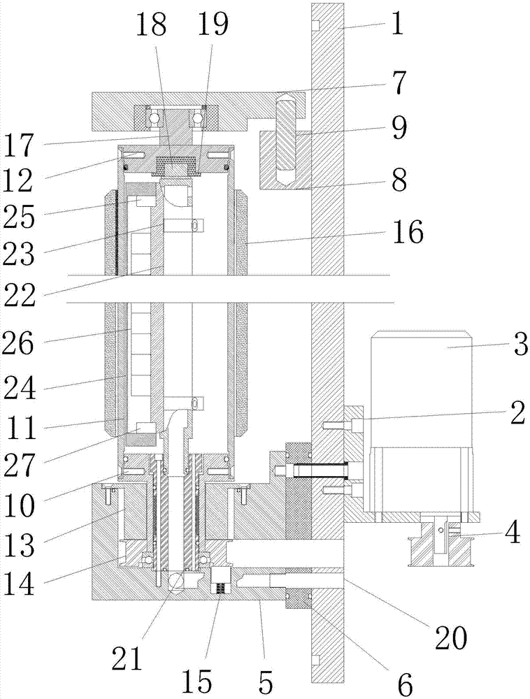
[0015] see figure 1 , in an embodiment of the present invention, a built-in rotating cathode structure includes a cathode gate 1, the cathode gate 1 is used in conjunction with a vacuum chamber, and the ultimate vacuum of the cathode gate 1 is 10 -5Pascal, and the working vacuum range is 0.01-10 Pascal, the lower end of one side of the cathode door 1 is provided with a motor seat 2, and the motor seat 2 is fixed on the cathode door 1 by bolts; the upper end of...


PUM


Abstract

The invention discloses a built-in rotary cathode structure. The built-in rotary cathode structure comprises a cathode door, wherein a motor seat is arranged at the lower end of one side of the cathode door; a target motor is arranged at the upper end of the motor seat and is fixedly mounted on the motor seat; a synchronizing wheel is arranged at the lower end of the motor seat; a lower end seat and an upper end seat are arranged on the other side of the cathode door; a lower end cap, a target tube and an upper end cap are arranged at the upper end of the lower end seat; the synchronizing wheel is fixedly connected with the lower end cap; and magnetic fluid is arranged at the lower end of the lower end cap. The target tube of the built-in rotary cathode structure is rotary, so that a target surface has a self-cleaning function; the utilization rate of a target material is high, a magnetic pole piece is slender, and uniformity of the thickness of a deposited film is improved; a magnetic fluid sealing design is adopted, the built-in rotary cathode structure is suitable for a production process for batch production, and modular design of a vacuum cavity of a large-area production line is facilitated; and the length of the whole magnetic pole piece can be increased according to the process, the structure of the cathode door is good in universality, the utilization rate of the target material is high, and process stability is also high.

Description

technical field [0001] The invention relates to the technical field of magnetron sputtering, in particular to a built-in rotating cathode structure. Background technique [0002] As a very effective thin film deposition method, magnetron sputtering technology is widely used in the fields of microelectronics, optical thin film and material surface treatment, for thin film deposition and surface coating preparation, and the industrialization of magnetron sputtering technology The application makes the improvement of the magnetron sputtering cathode extensive and widespread. In order to pursue the work stability of the production line, the process stability, the precise control of the film thickness and the versatility of the equipment, etc., the magnetron sputtering cathode has been carried out. Lots of improvements. In order to meet the needs of large-scale batch production lines, the rotating cathode structure has been widely valued and improved due to its characteristics o...

Claims


Application Information

Patent Timeline
IPC IPC(8): C23C14/35
CPCC23C14/3407C23C14/35
Inventor 朱选敏郭爱云李烁
Owner 武汉玖亿智能科技有限公司
Why Eureka
Try Eureka