Eureka AIR delivers breakthrough ideas for toughest innovation challenges, trusted by R&D personnel around the world.

Mechanical paw

A technology of mechanical claws and rotating shafts, applied in the field of mechanical claws, can solve the problems of small grasping force, wear, and inaccurate control, and achieve the effects of increased torque, long life, and precise transmission

Active Publication Date: 2017-08-18
FOSHAN UNIVERSITY
View PDF9 Cites 12 Cited by
  • Summary
  • Abstract
  • Description
  • Claims
  • Application Information

AI Technical Summary

Problems solved by technology

An important part of modern robots is the manipulator grasping, but the existing manipulator structure design is unreasonable, the grasping force is small, and the control is not precise. It often requires a lot of debugging before use, which is time-consuming and labor-intensive.
[0003]Furthermore, when the current robot grabs products of different sizes, its fingers can only grab products of a certain size in parallel, while other However, the product cannot be grasped in parallel, which leads to the occurrence of unstable grasping. The usual technical means of those skilled in the art is to set soft materials such as cushions to achieve grasping, but such cushions are prone to partial transition, wear and tear. It also makes the product stress uneven

Method used

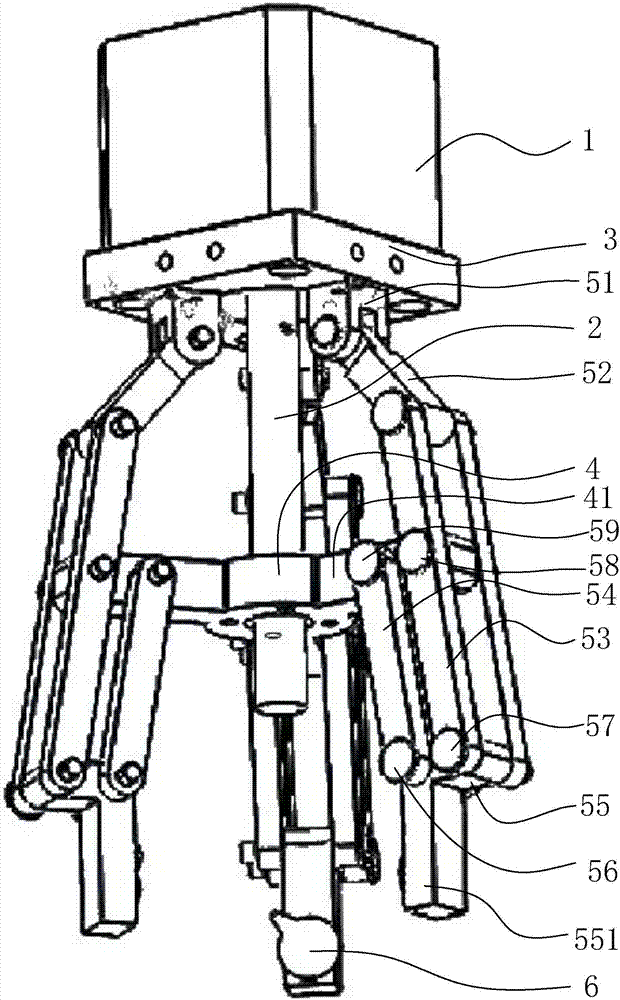

Image

  • Mechanical paw
  • Mechanical paw

Examples


Embodiment Construction

[0017] The idea, specific structure and technical effects of the present invention will be clearly and completely described below in conjunction with the embodiments and accompanying drawings, so as to fully understand the purpose, features and effects of the present invention. Apparently, the described embodiments are only some of the embodiments of the present invention, rather than all of them. Based on the embodiments of the present invention, other embodiments obtained by those skilled in the art without creative efforts belong to The protection scope of the present invention. In addition, all the connection / connection relationships mentioned in this article do not refer to the direct connection of components, but mean that a better connection structure can be formed by adding or reducing connection accessories according to specific implementation conditions. The various technical features in the present invention can be combined interactively on the premise of not confli...


PUM


Abstract

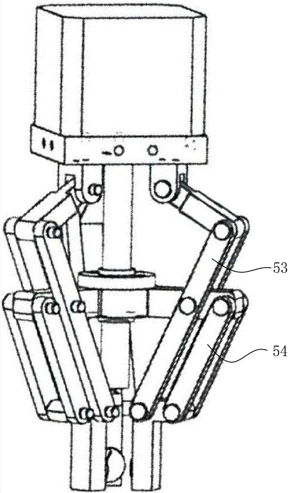
The invention discloses a mechanical paw. A driving module can drive a lead screw to rotate. In the rotating process of the lead screw, a servo lead screw nut will move up and down, and therefore the included angle formed between a first rod and a second rod is changed. According to the principle of parallelogram, a linkage rod connected with a third rod will produce displacement in the horizontal direction, and therefore clamping is achieved. Due to the fact that each driving component is of a simple connection rod structure, reliability is quite high, the service life is quite long, transmission of the servo lead screw nut and the driving lead screw is quite precise, and therefore the mechanical paw can achieve accurate clamping. Meanwhile, the servo lead screw nut and the driving lead screw can achieve the effects of reducing the speed and increasing torque and clamping force. Accordingly, the problems that an existing mechanical paw is large in size and high in weight as the existing mechanical paw needs to be additionally provided with a speed reducing mechanism is avoided.

Description

technical field [0001] The invention relates to a mechanical claw. Background technique [0002] The manipulator is the earliest industrial robot and the earliest modern robot. It can replace the heavy labor of people to realize the mechanization and automation of production, and can operate in harmful environments to protect personal safety. An important part of modern robots is the manipulator grasping, but the existing manipulator structure design is unreasonable, the grasping force is small, and the control is not precise. It often requires a lot of debugging before use, which is time-consuming and labor-intensive. [0003] Furthermore, when the current robot is grabbing products of different sizes, its fingers can only grab products of a certain size in parallel, but cannot grab other products in parallel, which leads to unstable gripping The common technical means of those skilled in the art is to set up soft materials such as cushions to achieve grasping, but such cu...

Claims


Application Information

Patent Timeline
Patent Type & Authority Applications(China)
IPC IPC(8): B25J15/02B25J15/10
CPCB25J15/022B25J15/10
Inventor 元祺龙卢清华
Owner FOSHAN UNIVERSITY
Why Eureka
Eureka Blog
Learn More