Large-torque medical trolley caster sleeving structure

A high-torque, caster technology, applied in the field of medical equipment, can solve the problems of inability to achieve quick fit, poor bearing strength of casters, and difficult to guarantee quality, achieve light disassembly, simplify assembly difficulty, and improve compressive and bending strength. Effect

Pending Publication Date: 2017-08-18
杨骏成
View PDF8 Cites 0 Cited by
  • Summary
  • Abstract
  • Description
  • Claims
  • Application Information

AI Technical Summary

Problems solved by technology

[0006] The existing caster structures are all fixed structures, which cannot be quickly assembled on site. Due to the large size of the entire vehicle, and the trolleys are all transported by the entire vehicle, the transportation cost is high
[0007] To sum up, there are many defects in the installation structure of existing casters, resulting in poor load-bearing strength of casters, short service life, cumbersome assembly, difficult quality assurance, and high labor intensity. How to improve the shortcomings of existing products has become an urgent need to solve question

Method used


Image

  • Large-torque medical trolley caster sleeving structure
  • Large-torque medical trolley caster sleeving structure
  • Large-torque medical trolley caster sleeving structure

Examples


Embodiment 1

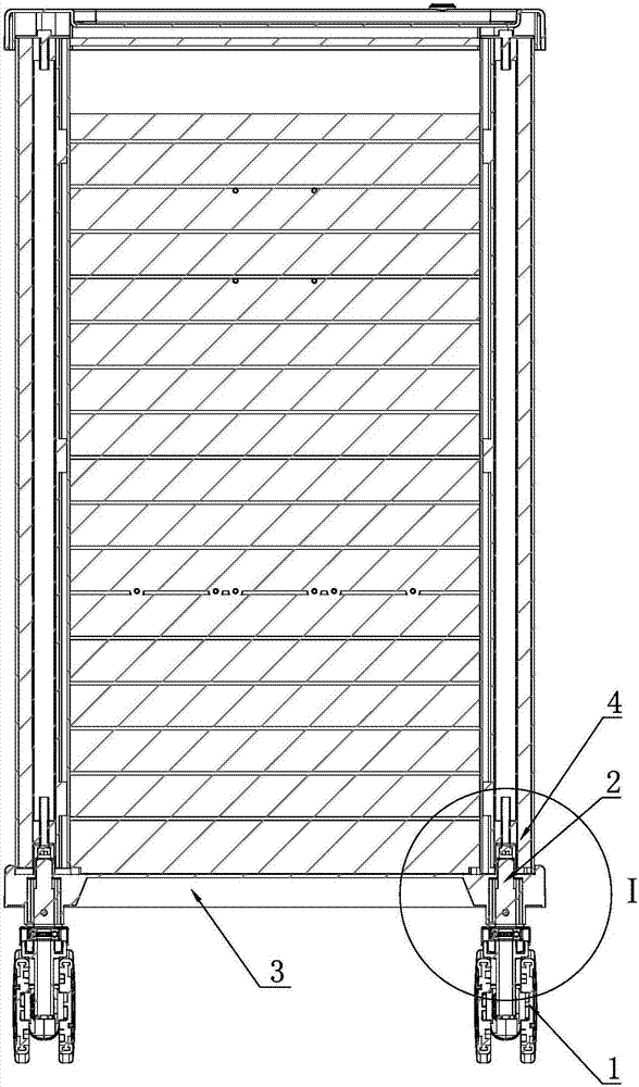
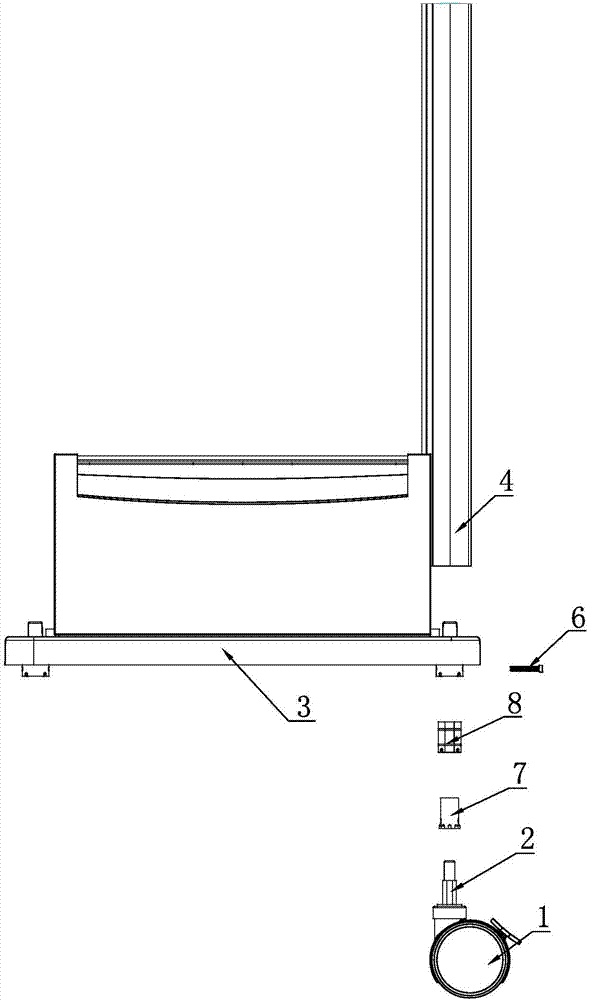
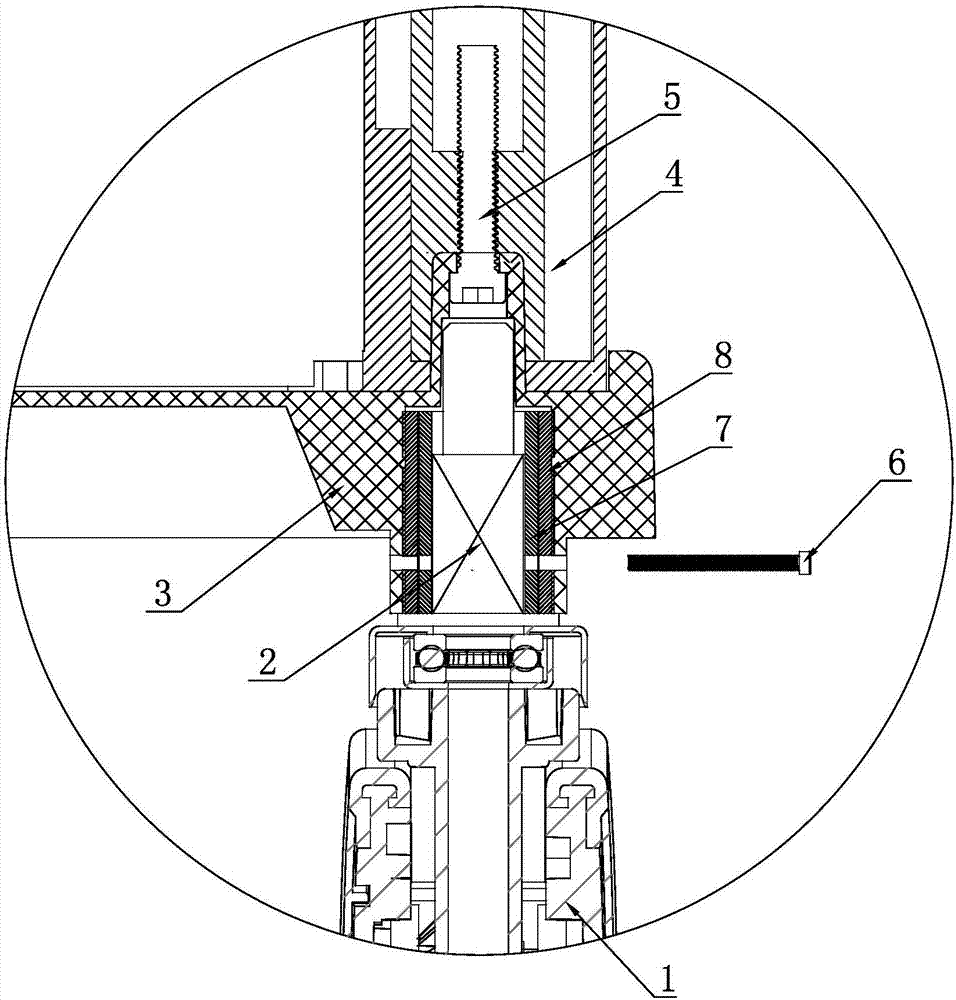
[0035] Embodiment 1: A high-torque medical cart caster set structure, such as Figure 1 to Figure 11 As shown, it includes a caster 1, a caster connecting shaft 2, a frame bottom plate 3, a frame pull tube 4, a fixing screw 5, an axial pin 6, a circumferential limit sleeve 7 and a frame column 9, and the caster is connected The shaft 2 includes a circumferential limiting shaft section 21 and a torque enhancing shaft section 22, and the cross-sectional shape of the circumferential limiting shaft section 21 is as follows: Figure 5 As shown, that is, the figure column is cut into a plane, and a pin hole 23 is provided on the plane. The torque enhancing shaft section 22 is arranged above the circumferential limiting shaft section 21, and the caster connecting shaft 2 passes through the circumferential limiting shaft section 21. Fixedly connected to the top of the caster 1; on the upper end surface of the four corners of the frame base plate 3 is provided with an upper positioning...

Embodiment 2

[0036] Embodiment 2: The difference from Embodiment 1 is that a conversion shock-absorbing sleeve 8 is embedded in the inner hole of the lower positioning sleeve 32 of the frame bottom plate 3, and the circumferential limit sleeve 7 is set on the conversion shock-absorbing sleeve 8. In the inner hole, the axial engagement between the lower end surface of the circumferential limiting sleeve 7 and the lower end shoulder of the conversion damping sleeve 8 is realized through a rectangular concave-convex joint block.

[0037] In the above two embodiments, the cross-sectional shape of the circumferential limiting shaft section 21 can be changed, and Figure 6 to Figure 9 Either of those will do.


PUM


Abstract

The invention discloses a large-torque medical trolley caster sleeving structure which comprises casters, caster connecting shafts, a frame bottom plate, frame pull tubes, fastening screws, axial pins and peripheral limit sleeves. The caster connecting shafts comprise peripheral limit shaft sections and torque enhancement shaft sections, upper positioning sleeve seats and lower positioning sleeve seats are arranged at four corners of the frame bottom plate, the outer diameter of each upper positioning sleeve seat corresponds to an inner hole of each frame pull tube, the peripheral limit sleeves are arranged in inner holes of the lower positioning sleeve seats, the sectional shape of an inner hole of each peripheral limit sleeve corresponds to that of each peripheral limit shaft section, a connecting nut is arranged in an inner hole of each frame pull tube, the lower ends of the frame pull tubes are inserted into the upper positioning sleeve seats of the frame bottom plate and axially and fixedly connected by the fastening screws, and the caster connecting shafts and the peripheral limit sleeves are axially limited by the axial pins. The bearing strength of the casters is enhanced, the casters can be conveniently sleeved in a bare-handed manner on site, loosening, falling and joint breakage of the casters are avoided when large resistance is applied to the casters, and the casters are long in service life.

Description

[0001] Technical field: [0002] The invention relates to medical equipment, in particular to a medical trolley, and more particularly to a caster installation structure of the medical trolley. [0003] Background technique: [0004] At present, the caster installation structure of medical carts is flat casters or screw casters. Usually, medical carts with metal bodies use screw casters, while medical carts with injection molded bodies use flat casters. The installation structure of the screw caster is as follows: a metal nut is welded in the column tube of the trolley tripod, and the screw spindle of the caster is fixed in the nut in the column tube through the screw connection. This structure belongs to the cantilever beam force structure. When an obstacle is encountered, the bearing force of the caster is borne by the combination of the metal nut and the screw rod. The limit torque it can withstand is small, and it is easy to cause the welding point of the nut to tear and be...

Claims


Application Information

Patent Timeline
IPC IPC(8): A61G12/00
CPCA61G12/001
Inventor 杨骏成
Owner 杨骏成
Why Eureka
Try Eureka