Tapered beam CT (computed tomography) imaging system based on attenuation plate
A technology of CT imaging and cone beam, which is applied in the fields of radiodiagnostic instruments, radiodiagnostic image/data processing, medical science, etc., and can solve the problems of limiting the effect of descattering and clinical application
- Summary
- Abstract
- Description
- Claims
- Application Information
AI Technical Summary
Problems solved by technology
Method used
Image
Examples
Embodiment 1
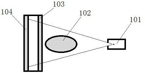
[0016] The invention discloses a cone-beam CT imaging system based on an attenuation plate. The imaging system is composed of an imaging device and image reconstruction software. The imaging device includes a frame and an x-ray source (101), an attenuation plate (103) and a flat panel detector (104) fixed on the frame. The X-rays emitted by the X-ray source (101) pass through the imaging target (102) and the attenuation plate (103) and are imaged on the flat panel detector (104) (see figure 1 ). When the imaging system collects images, the gantry rotates around the imaging target to obtain projection images from different angles of the imaging target. An attenuation plate (103) of uniform material is arranged between the imaging target (102) and the flat panel detector (104), and the attenuation plate has no gaps or holes. During the frame rotation process, the attenuation plate (103) rotates with the frame, and the distance between the attenuation plate (103) and the flat p...
Embodiment 2
[0019] In this embodiment, the hardware part is the same as Embodiment 1 except the attenuation plate (see figure 2 ). The attenuation plate (201) in this embodiment is a uniform water-equivalent density material, because the center of the image often has a larger proportion of scattered rays, so the surface of the attenuation plate is designed as an arc, with a greater thickness in the middle for better Good at blocking scattered rays. For a 100KeV X light source, the thickness of the attenuation plate is 2.5mm at the edge and 3.5mm at the center (see figure 2 Schematic diagram of the cross-section of the lower attenuation plate).
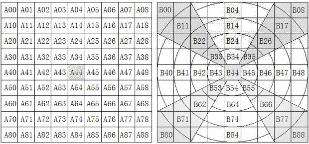
[0020] The scattering contribution matrix of a pencil beam chief ray on a flat panel detector is usually image 3 In the form on the left, A44 is the center of the pencil beam, which means that the scattering contribution of the pencil beam to all pixels (or pixels after downsampling) must be calculated, and the calculation is very heavy. In...
Embodiment 3
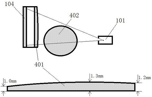
[0023] Many cone-beam CTs have full-fan and half-fan scanning modes. The full-fan mode is usually used for smaller imaging targets, and the half-fan mode is required for larger imaging targets. Both Embodiment 1 and Embodiment 2 are full-fan scans, and the flat panel detector is in the central position. This embodiment is a half-fan scan with the flat panel detector offset to one side (see Figure 4 ), the attenuation plate (401) is made of uniform tungsten material, the surface is eccentric arc surface, the thickest part is 1.3mm, the thickness of the thinner edge is 1.0mm, and the thickness of the thicker edge is 1.2mm (see Figure 4 Schematic diagram of the cross-section of the lower attenuation plate). In the half-fan scanning mode, projections of more than half of the imaging target (402) can be obtained for each projection image, and a 360-degree projection image needs to be collected for the entire scan. The method of calculation and removal of scattered rays is the s...
PUM
| Property | Measurement | Unit |
|---|---|---|
| Thickness | aaaaa | aaaaa |
| Thickness | aaaaa | aaaaa |
Abstract
Description
Claims
Application Information
 - Generate Ideas
- Intellectual Property
- Life Sciences
- Materials
- Tech Scout
- Unparalleled Data Quality
- Higher Quality Content
- 60% Fewer Hallucinations
Browse by: Latest US Patents, China's latest patents, Technical Efficacy Thesaurus, Application Domain, Technology Topic, Popular Technical Reports.
© 2025 PatSnap. All rights reserved.Legal|Privacy policy|Modern Slavery Act Transparency Statement|Sitemap|About US| Contact US: help@patsnap.com


