signal processing device
A signal processing device and input signal technology, applied in the direction of electrical digital data processing, input/output process of data processing, instruments, etc.
- Summary
- Abstract
- Description
- Claims
- Application Information
AI Technical Summary
Problems solved by technology
Method used
Image

Examples
Embodiment approach 1
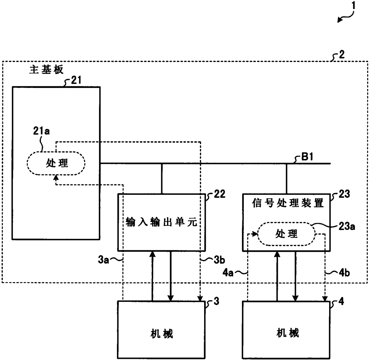
[0037] figure 1 It is a diagram showing the hardware configuration of an industrial system including the signal processing device according to the first embodiment.
[0038] The industrial system 1 includes: machines 3 and 4 that execute industrial processes exemplified by product manufacturing; and a programmable controller (JIS (Japanese Industrial Standards, Japanese Industrial Standards) B3502:2011, programmable controller) that controls the machines 3 and 4 controllers (PLC))2.
[0039] The programmable controller 2 includes a main board 21 , an input / output unit 22 connected to the main board 21 via a bus B1 , and a signal processing device 23 . The input / output unit 22 and the signal processing device 23 are respectively sub-boards of the programmable controller 2 .
[0040] The input / output unit 22 is connected to the machine 3 and is a transceiver for transmitting data input from the machine 3 to the main board 21 and outputting data received from the main board 21 ...
Embodiment approach 2
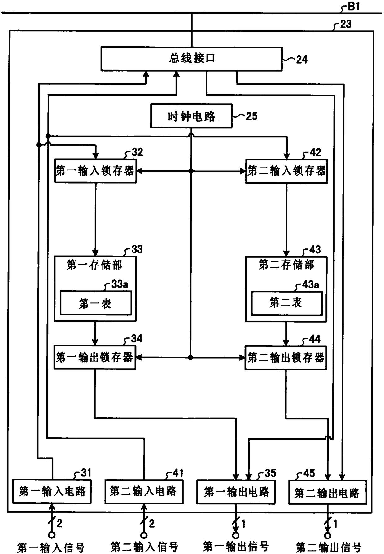
[0098] Figure 6 It is a diagram showing the hardware configuration of the signal processing device according to the second embodiment.
[0099] and figure 2 Compared with the signal processing device 23 according to the first embodiment shown, the signal processing device 23A according to the second embodiment further includes a determination unit 26 as a logic circuit.
[0100] The determination unit 26 performs logical operation on the signal input from the first output latch 34 and the signal input from the second output latch 44, outputs the first output signal obtained by the logical operation to the first output circuit 35, and outputs the first output signal obtained by the logical operation to the first output circuit 35. The second output signal obtained by logical operation is output to the second output circuit 45 .
[0101] Figure 7 It is a figure which shows the truth table of the logical operation performed by the determination part of the signal processing...
Embodiment approach 3
[0111] Figure 8 It is a diagram showing the hardware configuration of the signal processing device according to the third embodiment.
[0112] and figure 2 Compared with the signal processing device 23 according to the first embodiment shown, the signal processing device 23B according to the third embodiment further includes a determination unit 28 as a logic circuit.
[0113] The determination unit 28 includes a collating circuit 28a. The collation circuit 28 a is a logic circuit that executes a logic operation that collates whether or not the first input signal input from the first input latch 32 and the second input signal input from the second input latch 42 coincide.
[0114] The determination unit 28 includes a first AND (logical AND) circuit 28b. The first AND circuit 28b performs a logical AND operation of the output signal of the first output latch 34 and the output signal of the collation circuit 28a, and outputs a first output signal which is a result signal of...
PUM
 Abstract
Description
Claims
Application Information
 - R&D
- Intellectual Property
- Life Sciences
- Materials
- Tech Scout
- Unparalleled Data Quality
- Higher Quality Content
- 60% Fewer Hallucinations
Browse by: Latest US Patents, China's latest patents, Technical Efficacy Thesaurus, Application Domain, Technology Topic, Popular Technical Reports.
© 2025 PatSnap. All rights reserved.Legal|Privacy policy|Modern Slavery Act Transparency Statement|Sitemap|About US| Contact US: help@patsnap.com