Device for regulating a coolant flow and cooling system

A technology of cooling medium flow and cooling system, used in the control of coolant flow, engine cooling, non-variable-capacity pumps, etc., can solve problems such as hindering the heating of the combustion chamber, and achieve the effect of fail-safe functions

Inactive Publication Date: 2012-05-16
SCHAEFFLER TECH AG & CO KG
View PDF4 Cites 3 Cited by
  • Summary
  • Abstract
  • Description
  • Claims
  • Application Information

AI Technical Summary

Problems solved by technology

In contrast, in the case of a cold start of the internal combustion engine, the problem arises that the cooling medium already circulating through the cooling ducts hinders the heating up of the combustion chamber and thus delays reaching the optimum operating temperature

Method used


Image

  • Device for regulating a coolant flow and cooling system
  • Device for regulating a coolant flow and cooling system
  • Device for regulating a coolant flow and cooling system

Examples


Embodiment Construction

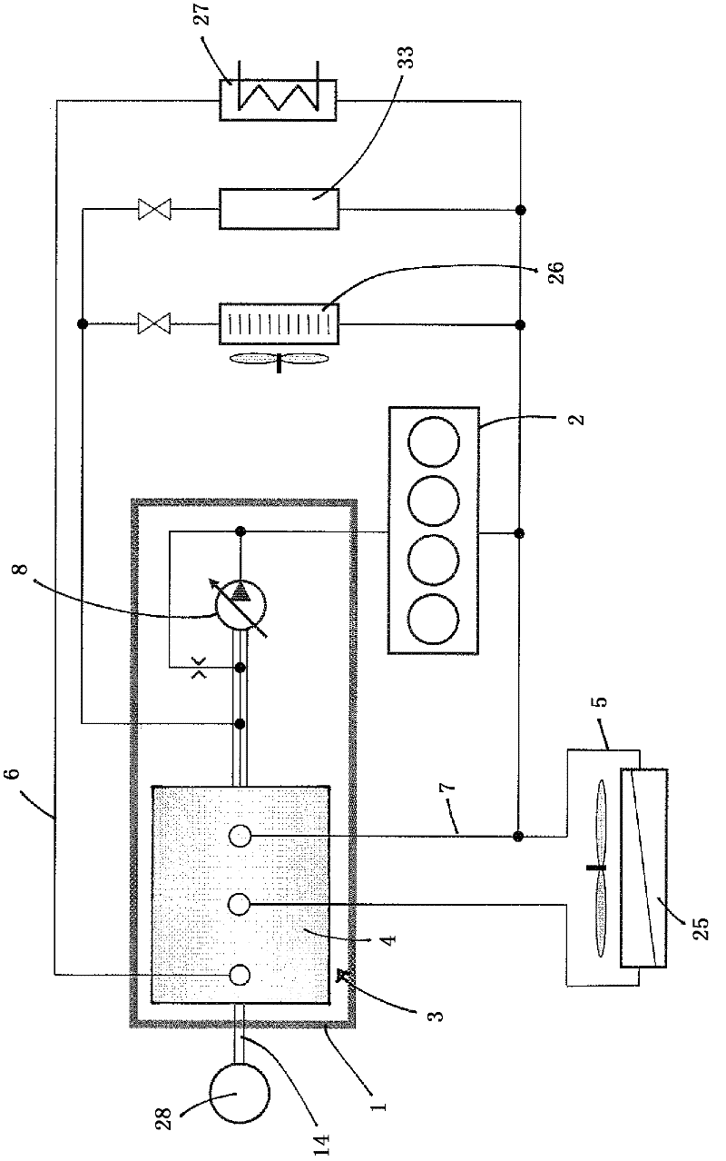
[0031] According to the cooling system of the present invention figure 1 The example shown in includes a device 1 for regulating a coolant flow, which device 1 can primarily be used for cooling an internal combustion engine 2 . Furthermore, an oil cooler 26 as a further consumer and a heating device 27 are connected to the cooling circuit. Furthermore, other components 33 can optionally be connected to the cooling system. In order to be able to achieve the desired distribution of the cooling medium flow, the cooling system also has various cooling circuits 5 , 6 and a bypass circuit 7 for enclosing the cooler 25 in the cooling circuit 5 . Thus, an uncooled coolant flow is already provided via the bypass circuit, which enables an optimum coolant temperature to be set. For this purpose, the cooling medium from the bypass circuit 7 is mixed with the cooling medium from the cooling circuit 5 . The mixing takes place via the valve system 3 , which is a component of the device 1 ...


PUM


Abstract

A device (1) for regulating a coolant flow in a cooling system of an internal combustion engine (2) with a valve arrangement (3) that includes a rotary disk valve (4) for switching at least one cooling circuit (5, 6) and / or a bypass circuit (7), as well as a coolant pump (8) that is constructed as an impeller pump and is connected on the suction side to the valve arrangement (3). The coolant pump (8) has an axial adjustable guide plate (11) on an inside between two end stops (9, 10) for closing and releasing a pump outlet (12). The guide plate (11) for the axial adjustment is indirectly coupleable by a lead screw thread (13) to a drive shaft (14) of the rotary disk valve (4). A cooling system for an internal combustion engine (2) with such a device (1) is also provided.

Description

technical field [0001] The invention relates to a device for regulating the flow of a cooling medium in a cooling system of an internal combustion engine, having the features of the preamble of claim 1 . Furthermore, the invention also relates to a cooling system with such a device. Background technique [0002] Today, internal combustion engines are essentially cooled with water. For this purpose, cooling water is pumped into a closed circuit by means of a cooling medium pump or a cooling water pump through cooling ducts in the cylinder area in order to cool the internal combustion engine and is then conveyed to the air-water cooler, where it is heated The warm water is cooled down again by the driving wind. The pumps required for circulating the water are preferably driven by the internal combustion engine. For this purpose, the pump is usually connected via a belt to the pulley of the crankshaft of the internal combustion engine. [0003] In this case, the direct coup...

Claims


Application Information

Patent Timeline
IPC IPC(8): F01P7/16F01P5/12F04D15/00
CPCF01P7/162F04D15/0038F01P7/165F04D15/0016
Inventor 马库斯·波普爱德华·戈洛瓦泰-施米特沃尔夫冈·莱克托马斯·特劳德塞巴斯蒂安·赫斯特
Owner SCHAEFFLER TECH AG & CO KG
Why Eureka
Try Eureka