Hydraulic control apparatus for automatic transmission

An automatic transmission and oil pressure control technology, which is applied in the direction of engine control, transmission control, and components with teeth, etc., can solve the problems of large-scale automatic transmission and complex oil circuit structure, etc.

Inactive Publication Date: 2011-04-06
AISIN AW CO LTD
View PDF4 Cites 4 Cited by
  • Summary
  • Abstract
  • Description
  • Claims
  • Application Information

AI Technical Summary

Problems solved by technology

However, in order to realize different shift speeds at the time of fail-safe by reverse input as described above, the structure of the oil circuit becomes more complicated, which leads to a problem of increasing the size of the automatic transmission.

Method used


Image

  • Hydraulic control apparatus for automatic transmission
  • Hydraulic control apparatus for automatic transmission
  • Hydraulic control apparatus for automatic transmission

Examples


Embodiment Construction

[0028] follow below Figure 1 ~ Figure 4 Embodiments of the present invention will be described.

[0029] [Outline structure of automatic transmission]

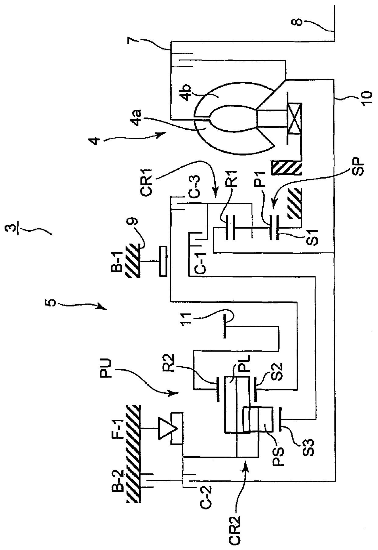
[0030] First, follow the figure 1 A schematic structure of the automatic transmission 3 to which the present invention can be applied will be described. Such as figure 1 As shown, for example, an automatic transmission 3 suitable for FF type (front-engine, front-wheel drive) vehicles has an input shaft 8 of the automatic transmission 3 that can be connected to an engine (not shown), and the axial direction of the input shaft 8 It has a hydraulic torque converter 4 and an automatic transmission mechanism 5 at the center.

[0031] The torque converter 4 has a pump impeller 4 a connected to the input shaft 8 of the automatic transmission 3 and a turbine 4 b that transmits the rotation of the pump impeller 4 a via a working fluid, and the turbine 4 b is connected to the input shaft of the automatic transmission mechanism 5 ....


PUM


Abstract

A first clutch applying relay valve (21) is, in a first to third forward stages, set to a low-speed stage position for outputting a first preliminary hydraulic pressure for a hydraulic servo (41) of a clutch (C-1) and is, in fourth to sixth forward stages, set to a high-speed stage position for outputting a second preliminary hydraulic pressure for a hydraulic servo (42) of a clutch (C-2). In a normal condition, a second clutch applying relay valve (22) supplies control hydraulic pressures from linear solenoid valves (SLC1, SLC2, SLC3) to hydraulic servos (41, 42, 43) of clutches (C-1, C-2, C-3). In an ALL-OFF failure, the second clutch applying relay valve (22) supplies the first preliminary hydraulic pressure or the second preliminary hydraulic pressure to the hydraulic servos (41, 42) and supplies a line pressure (PL) to the hydraulic servo (43). The configuration allows the linear solenoid valves (SLC1, SLC2, SLC3) to be of normally closed type and allows a low-speed stage or a high-speed stage to be achieved even when the solenoid valves are in the ALL-OFF condition.

Description

technical field [0001] The present invention relates to a hydraulic control device of an automatic transmission mounted on a vehicle, and more particularly to a hydraulic control device of an automatic transmission capable of shifting gears even in the event of a non-energized failure. Background technique [0002] Generally, in a multi-speed automatic transmission mounted on a vehicle or the like, the rotation state of each rotating member of the transmission gear mechanism is controlled according to the engagement state of a plurality of frictional engagement members, thereby forming each shift speed, which is engaged by using a solenoid valve. The pressure is electrically regulated and supplied to a hydraulic servo mechanism of each friction engagement element, thereby controlling the engagement state of the plurality of friction engagement elements described above. [0003] However, in the above-mentioned automatic transmission, when a failure occurs in which power canno...

Claims


Application Information

Patent Timeline
Patent Type & Authority Applications(China)
IPC IPC(8): F16H61/12F16H61/00F16H59/70
CPCF16H61/0206F16H61/686F16H2061/1232F16H2061/1268F16H61/12Y10S477/906
Inventor 清水哲也土田建一铃木明智石川和典
Owner AISIN AW CO LTD
Why Eureka
Try Eureka