Rod punching and shearing die

A punching and shearing and rod material technology, which is applied in the field of mechanical punching and shearing, can solve the problems of elbows at the cut, time-consuming, and reduce the production efficiency of the production line, and achieve the effect of flat section.

Active Publication Date: 2017-08-15
重庆永丰精气汽车配件有限公司
View PDF6 Cites 0 Cited by
  • Summary
  • Abstract
  • Description
  • Claims
  • Application Information

AI Technical Summary

Problems solved by technology

This manual tool change method takes a long time, about 1.5 hours to 2 hours, which greatly reduces the production efficiency of the entire production line
In addition, there is an elbow phenomenon at the cutting part of the punched rod material, and the problem that the cut section is not flat

Method used


Image

  • Rod punching and shearing die
  • Rod punching and shearing die

Examples


Embodiment Construction

[0014] The present invention will be described in further detail below by means of specific embodiments:

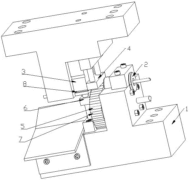
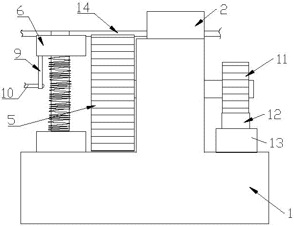
[0015] The reference signs in the drawings of the description include: base 1, material guide sleeve 2, upper punching block 3, upper pressing block 4, lower punching block 5, lower pressing block 6, punching groove 7, punching Groove 8, support bar 9, limit pin 10, driven gear 11, rack 12, cylinder 13, bar material 14.

[0016] The embodiment is basically as attached figure 1 Shown: rod material punching and shearing die, including base 1, material guide mechanism, material breaking mechanism and limit mechanism, material guide mechanism includes material guide sleeve 2 installed on base 1, and material guide sleeve 2 is equipped with There is a material guide hole for the rod material 14 to pass through, and the right end entrance of the material guide hole is in a flared shape gradually increasing to the right, and the material guide sleeve 2 guides the rod material 1...


PUM


Abstract

The invention relates to a rod punching and shearing die and relates to the field of mechanical punching and shearing. The rod punching and shearing die comprises a base, a material guiding mechanism and a material breaking mechanism. The material guiding mechanism comprises a material guiding sleeve installed on the base. The material guiding sleeve is internally provided with a material guiding hole allowing a rod to penetrate through. An inlet of the material guiding hole is in a flaring shape. The material breaking mechanism comprises a dynamic material breaking mechanism body and a static material breaking mechanism body. The dynamic material breaking mechanism body is installed on a punch and comprises an upper punching and shearing block and an upper pressing unit. The upper pressing unit comprises an upper pressing block. The static material breaking mechanism body comprises a lower punching and shearing block and a lower pressing unit. The lower punching and shearing block is rotationally connected to the base and is round. Punching and shearing grooves are circumferentially formed in the edge of the lower punching and shearing block. A rotating shaft is fixedly connected to the center of the lower punching and shearing block. A driven gear is coaxially connected to the rotating shaft. A rack is arranged on the driven gear in an engaged mode. An air cylinder is connected to the end of the rack. A lower pressing block is provided with a punching groove. By implementing the scheme, on-line switching of cutters and leveling of the rod sections in the prior art are achieved, and the problem that the cut positions of rods are deformed is solved.

Description

technical field [0001] The invention relates to the field of mechanical punching and shearing. Background technique [0002] The knives on the existing punching and shearing punching machine are divided into static knives and moving knives, and the static knives and the moving knives are used together. Before work, the punching, shearing and punching machine can move back and forth along the conveying direction of the production line under the drive of the servo system to adjust the position. When working, the profile passes continuously between the moving knife and the static knife. When the punching machine drives the moving knife down, the cooperation of the moving knife and the static knife will punch and shear the profile. [0003] In the current punching and shearing press, the static knife is installed and fixed on the static knife seat with the static knife fixing plate, the static knife seat is fixed on the frame, and the moving knife is installed on the moving kni...

Claims


Application Information

Patent Timeline
IPC IPC(8): B21D28/14
CPCB21D28/14
Inventor 张进涛
Owner 重庆永丰精气汽车配件有限公司
Why Eureka
Try Eureka