High-efficiency boiler dedusting desulfurization denitrification device

A technology for desulfurization, denitrification, and dust removal devices, which is applied in gas treatment, membrane technology, and dispersed particle separation. The effect of low range requirements, reduction of circulating water volume, and strong adaptability

Inactive Publication Date: 2017-08-15
鲍守明 +1
View PDF23 Cites 2 Cited by
  • Summary
  • Abstract
  • Description
  • Claims
  • Application Information

AI Technical Summary

Problems solved by technology

[0002] Existing boiler flue gas purification devices generally use the lime-gypsum method for desulfurization and denitrification, which has high operating costs, desulfurization and denitrification efficiency is not high enough, and the removal rate is not ideal
This kind of flue gas purification device generally uses a cloth bag to remove dust from the initial flue dust. The bag dust removal has strict requirements on the temperature range of the flue gas. If the temperature exceeds 180 degrees, the bag is easy to burn, and if the temperature is lower than 70 degrees, it is easy to condense and block the bag, which is not conducive to reducing the temperature of the boiler. Flue gas temperature improves thermal efficiency to achieve the purpose of energy saving and emission reduction
The operating cost of bag dust removal is also relatively high, and it takes 2-3 years to replace the new bag to achieve effective dust removal effect

Method used


Image

  • High-efficiency boiler dedusting desulfurization denitrification device
  • High-efficiency boiler dedusting desulfurization denitrification device
  • High-efficiency boiler dedusting desulfurization denitrification device

Examples


Embodiment Construction

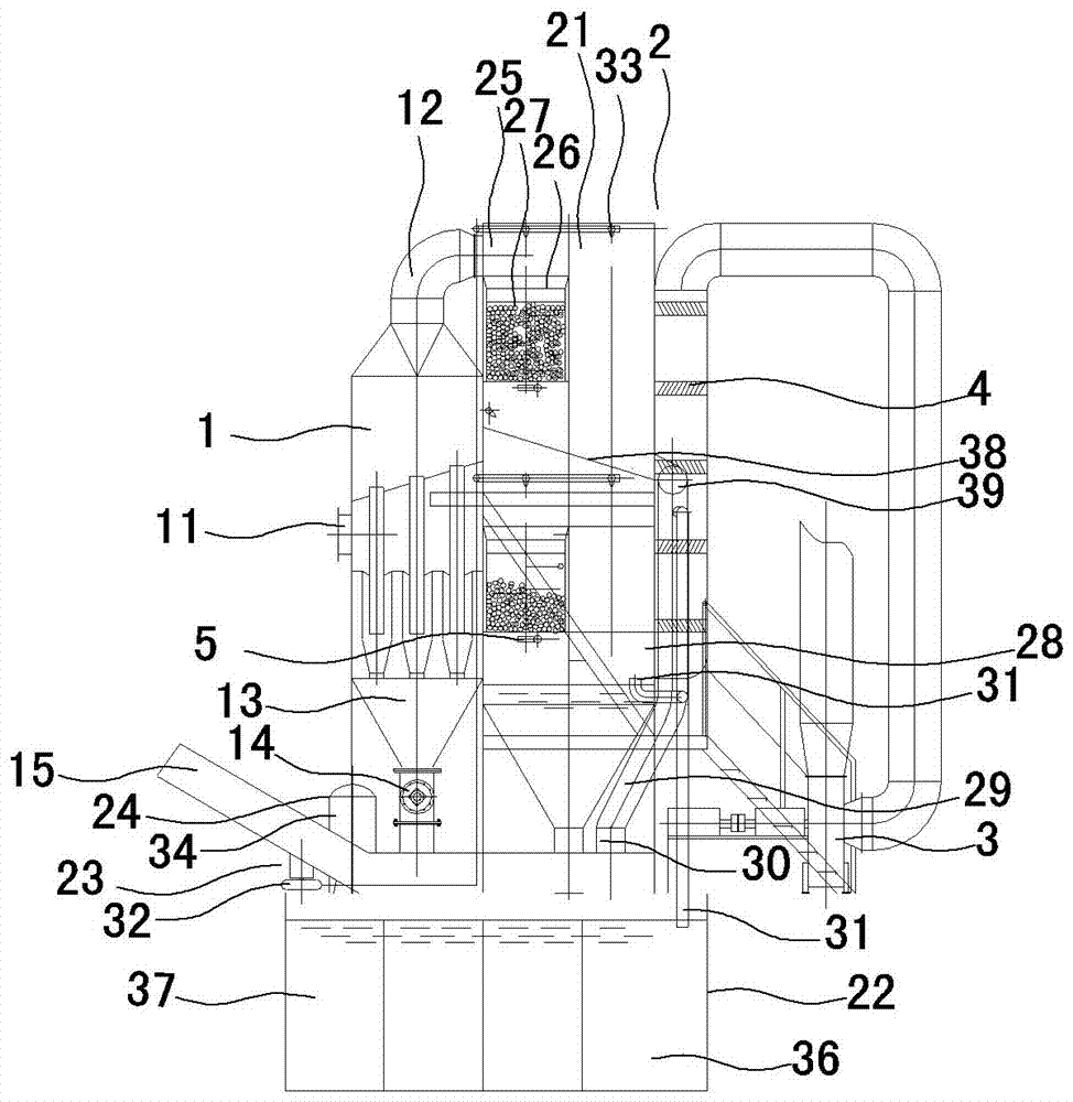
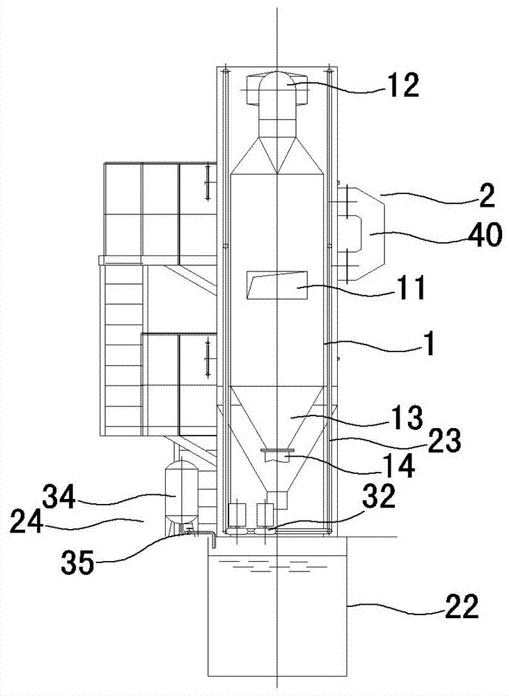
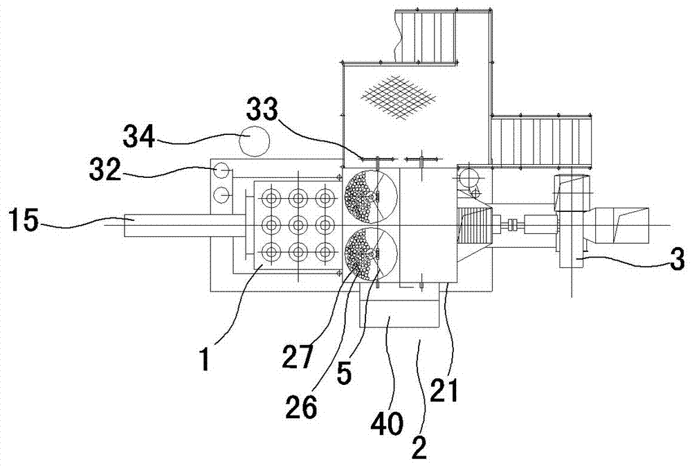
[0010] like figure 1 , figure 2 , image 3 As shown, it includes a dust removal device 1, a desulfurization and denitration device 2 and an induced draft fan 3. The dust removal device 1 is provided with a total air inlet 11 along the tangential direction of the side wall, a total air outlet 12 on the upper part, and an ash collecting hopper 13 at the bottom. The outlet of the ash collecting hopper 13 is provided with a cyclone multi-tube dust collector with an ash discharge valve 14. The desulfurization and denitrification device 2 is composed of a desulfurization and denitrification tower 21, a circulating sedimentation tank 22, a urea spray mechanism 23 and a dosing mechanism 24. The cyclone multi-tube The air outlet 12 of the dust collector is communicated with the flue gas inlet 25 above the desulfurization and denitrification tower 21. The circulating sedimentation tank 22 is located below the desulfurization and denitrification tower 21. The desulfurization and denitr...


PUM

PropertyMeasurementUnit
diameteraaaaaaaaaa
diameteraaaaaaaaaa
diameteraaaaaaaaaa

Abstract

The invention relates to a high-efficiency boiler dedusting desulfurization denitrification device. The high-efficiency boiler dedusting desulfurization denitrification device comprises a dedusting device (1), a desulfurization denitrification device (2), and an induced draft fan (3); the desulfurization denitrification device is composed of a desulfurization denitrification tower (21), a circulation sedimentation tank (22), a urea spraying mechanism (23), and a drug adding mechanism (24); a wind outlet (12) of a cyclone multi-tube dust collector is communicated with a flue gas inlet (25) of the desulfurization denitrification tower; a plurality of raschig ring filter subassemblies (26) are arranged in the desulfurization denitrification tower; a flue gas outlet of the desulfurization denitrification tower is communicated with a wind inlet of the induced draft fan (3); the urea spraying mechanism (23) is composed of a circulating pump (32), and a plurality of spray nozzles (33) arranged in the desulfurization denitrification tower (21); the drug adding mechanism (24) is composed of a urea tank (34) and a drug adding pump (35). The high-efficiency boiler dedusting desulfurization denitrification device is high in desulfurization denitrification efficiency, and excellent in dedusting effect, and is capable of reducing boiler flue gas temperature and increasing boiler heat effciency; requirement on flue gas temperature range is low; and production operation cost is low.

Description

technical field [0001] The invention relates to a flue gas purification device, in particular to a dust removal, desulfurization and denitration device for purifying boiler flue gas. Background technique [0002] Existing boiler flue gas purification devices generally use the lime-gypsum method for desulfurization and denitrification, which has high operating costs, insufficient desulfurization and denitrification efficiency, and unsatisfactory denitrification rates. This kind of flue gas purification device generally uses a cloth bag to remove the initial smoke dust. The bag dust removal has strict requirements on the temperature range of the flue gas. When the temperature exceeds 180 degrees, the cloth bag is easy to burn, and it is easy to condense and block the bag when the temperature is lower than 70 degrees. The flue gas temperature improves thermal efficiency to achieve the purpose of energy saving and emission reduction. The operating cost of bag dust removal is al...

Claims


Application Information

Patent Timeline
Patent Type & Authority Applications(China)
IPC IPC(8): B01D45/16B01D53/78B01D53/60
CPCB01D45/16B01D53/60B01D53/78B01D2251/2067B01D2258/0283B01D2256/10B01D2257/302B01D2257/40B01D2256/22
Inventor 鲍守明陈懿修
Owner 鲍守明
Why Eureka
Try Eureka