
Camera exposure method and device

An exposure method and camera technology, applied in the field of cameras, can solve the problems of wasting drivers, light pollution energy, and operating errors, and achieve the effects of avoiding operating errors, avoiding light pollution, and saving energy

Active Publication Date: 2020-09-04
成都希格玛光电科技有限公司
View PDF8 Cites 0 Cited by
  • Summary
  • Abstract
  • Description
  • Claims
  • Application Information

AI Technical Summary

Problems solved by technology

The existing high-power LED supplementary light fixtures on the market for supplementary light have a fixed frequency or output light time, and cannot be accurately synchronized with various cameras when shooting, so that when the camera is shooting, it cannot , the camera cannot be supplemented with light when shooting, or the supplementary light cannot be accurately synchronized with the shooting of the camera, so that complete synchronization of exposure cannot be achieved, which affects the shooting effect of the camera, especially in traffic. The light is in a bright state for a long time; and the power of the supplementary light is high, which leads to light pollution and energy waste, and the high brightness of the supplementary light causes the driver to make mistakes; in addition, when shooting in foggy days, due to the lack of Defog function, resulting in unclear shooting effect

Method used


Image

  • Camera exposure method and device
  • Camera exposure method and device
  • Camera exposure method and device

Examples


Embodiment 1

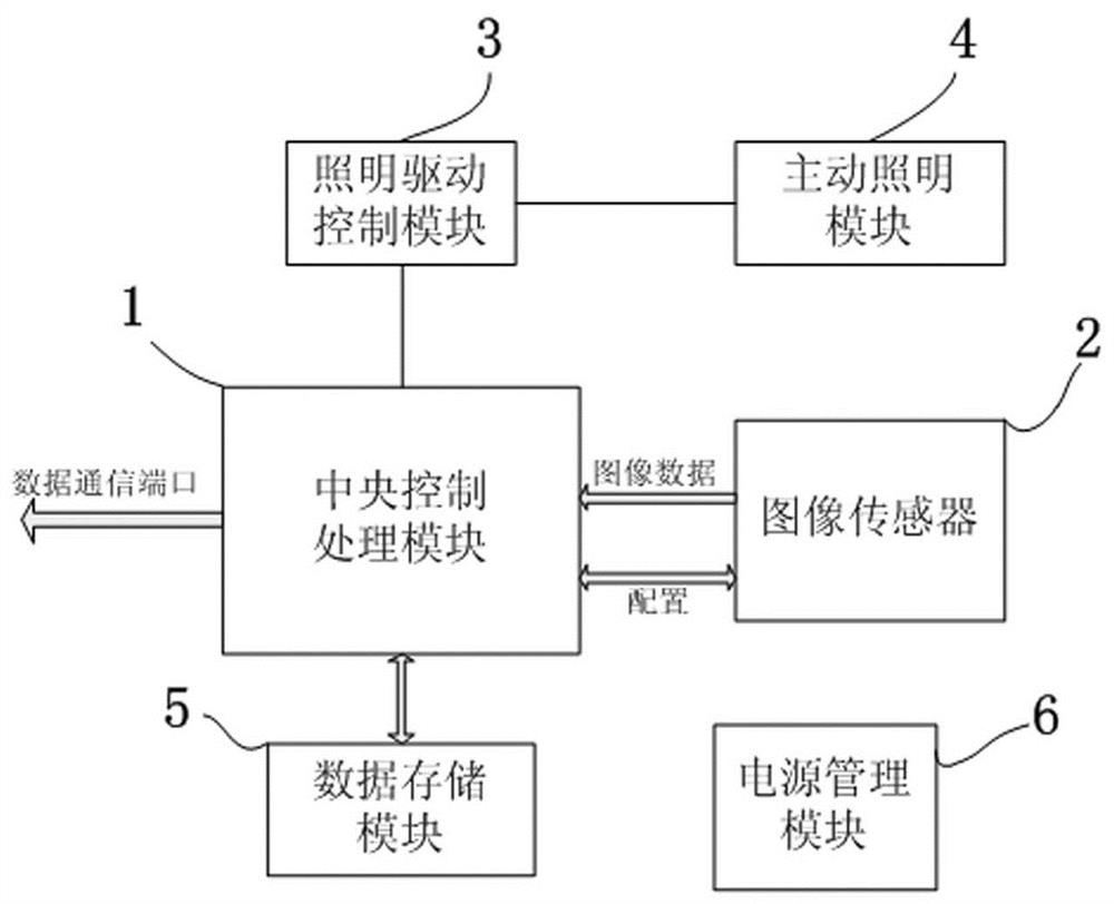
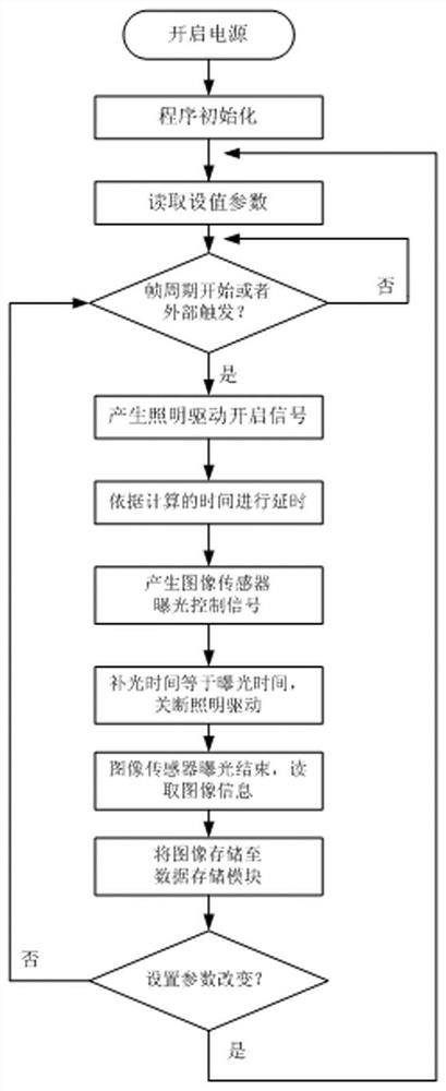
[0029] Such as Figure 1 to Figure 4 As shown, a camera exposure method, the target image is collected by the image sensor 2, and the collected target image is transmitted to the central control processing module 1, and the central control processing module 1 drives and controls the lighting drive control module 3, and generates a delay timing at the same time; The lighting drive control module 3 generates a signal to drive the active lighting module 4 after receiving the control input; the delay timing is:

[0030] △t=△t1+△t2+△t3

[0031] In the formula: △t1 is the fixed delay time of the lighting drive control module 3;

[0032] Δt2 is the fixed delay time of the active lighting module 4;

[0033] Δt3 is the optical path time difference; Δt3 =2S / c; c is the speed of light, 2S is the sum of the distance between the active lighting module 4 and the object to be photographed and the distance reflected from the object to be photographed to the image sensor 2;

[0034] Δt is t...

Embodiment 2

[0057] Such as Figure 1 to Figure 4 Shown, a kind of camera exposure device comprises:

[0058] The image sensor 2 takes an image of an object with an exposure time set.

[0059] The active lighting module 4 is set with a lighting time for generating light to illuminate objects, the lighting time is equal to the exposure time of the image sensor 2, and the active lighting module 4 has a fixed delay time Δt2.

[0060] The lighting drive control module 3 is used to drive the active lighting module 4 to work, and the lighting drive control module 3 has a fixed delay time Δt1.

[0061] The central control processing module 1 is used to calculate the delay timer Δt, and command the lighting drive control module 3 to start working, and the time point of issuing the command is Δt earlier than the time point when the image sensor 2 starts working.

[0062] △t=△t1+△t2+△t3

[0063] Δt3 is the optical path time difference; Δt 3=2S / c; c is the speed of light, and 2S is the distance be...


PUM


Abstract

The invention discloses a camera exposure method and device. The target image is collected by an image sensor, and the collected target image is transmitted to a central control processing module. The central control processing module drives and controls the lighting drive control module, and simultaneously generates a delay timing; lighting The drive control module generates a signal to drive the active lighting module after receiving the control input; when the delay timing is completed, the light signal sent by the active lighting module is reflected by the object to the image sensor, and the image sensor starts to expose. When the exposure time of the image sensor is equal to that of the active lighting module When the time is turned on, the image sensor completes the exposure, and the central control processing module reads the image information in the image sensor. The invention can make the supplementary light turn on time as long as the exposure time of the image sensor, can realize synchronous exposure, can not only avoid light pollution and save energy, but also avoid driver's misoperation caused by the high brightness of the supplementary light.

Description

technical field [0001] The invention relates to a camera, in particular to a camera exposure method and device. Background technique [0002] At present, there are many types and styles of cameras used in traffic, environmental safety monitoring, terrain exploration, spectral analysis, fog penetration monitoring, long-distance monitoring and other fields, and the specific capture of each camera is different. The existing high-power LED supplementary light fixtures on the market for supplementary light have a fixed frequency or output light time, and cannot be accurately synchronized with various cameras when shooting, so that when the camera is shooting, it cannot , the camera cannot be supplemented with light when shooting, or the supplementary light cannot be accurately synchronized with the shooting of the camera, so that complete synchronization of exposure cannot be achieved, which affects the shooting effect of the camera, especially in traffic. The light is in a brig...

Claims


Application Information

Patent Timeline
Patent Type & Authority Patents(China)
IPC IPC(8): H04N5/235
CPCH04N23/741H04N23/74
Inventor 邹泽亚李祥刘思远
Owner 成都希格玛光电科技有限公司
Learn More