Camera exposure method and apparatus
An exposure method and camera technology, applied in the field of cameras, can solve the problems of wasting drivers, light pollution energy, unable to fill light with cameras, etc., and achieve the effects of avoiding operation errors, avoiding light pollution, and synchronizing exposure.
- Summary
- Abstract
- Description
- Claims
- Application Information
AI Technical Summary
Problems solved by technology
Method used
Image
Examples
Embodiment 1
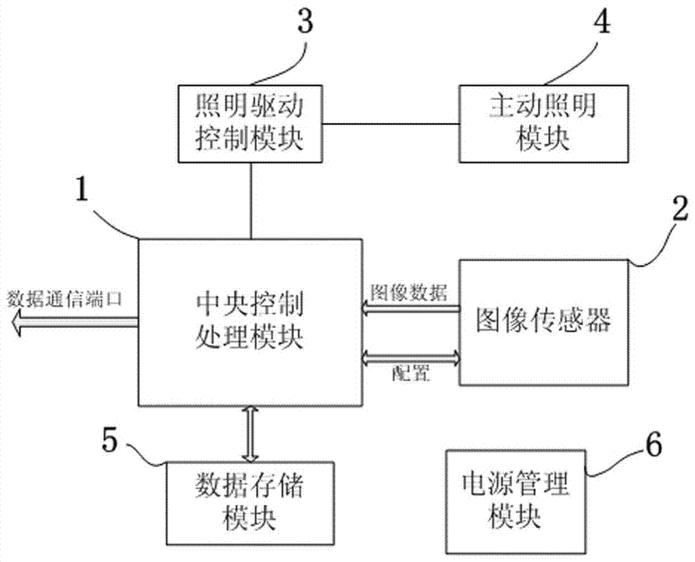
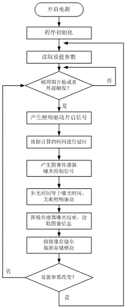
[0029] Such as Figure 1 to Figure 4 As shown, a camera exposure method collects a target image through an image sensor 2 and transmits the collected target image to a central control processing module 1. The central control processing module 1 drives and controls the lighting drive control module 3, and at the same time generates a delay timer; The lighting drive control module 3 generates a signal to drive the active lighting module 4 after receiving the control input; the delay time is:
[0030] △t=△t1+△t2+△t3
[0031] Where: △t1 is the fixed delay time of lighting drive control module 3;
[0032] △t2 is the fixed delay time of active lighting module 4;
[0033] △t3 is the optical path time difference; △t3 = 2S / c; c is the speed of light, 2S is the sum of the distance between the active lighting module 4 and the object being photographed and the reflection of the object to the image sensor 2;
[0034] △t is the delay timing time;
[0035] When the delay time is completed, the light ...
Embodiment 2
[0057] Such as Figure 1 to Figure 4 As shown, a camera exposure device includes:
[0058] The image sensor 2 is set with an exposure time to capture an object.
[0059] The active lighting module 4 is set with a lighting time for generating light to illuminate the object. The lighting time is equal to the exposure time of the image sensor 2, and the active lighting module 4 has a fixed delay time Δt2.
[0060] The lighting drive control module 3 is used to drive the active lighting module 4 to work, and the lighting drive control module 3 has a fixed delay time Δt1.
[0061] The central control processing module 1 is used to calculate the delay time Δt and instruct the lighting drive control module 3 to start working. The time point of this command is earlier than the time when the image sensor 2 starts working.
[0062] △t=△t1+△t2+△t3
[0063] △t3 is the light path time difference; △t 3=2S / c; c is the speed of light, 2S is the distance between the light source emitted by the active li...
PUM
 Abstract
Description
Claims
Application Information
 - R&D Engineer
- R&D Manager
- IP Professional
- Industry Leading Data Capabilities
- Powerful AI technology
- Patent DNA Extraction
Browse by: Latest US Patents, China's latest patents, Technical Efficacy Thesaurus, Application Domain, Technology Topic, Popular Technical Reports.
© 2024 PatSnap. All rights reserved.Legal|Privacy policy|Modern Slavery Act Transparency Statement|Sitemap|About US| Contact US: help@patsnap.com


