Phase-change material service life testing system

A phase change material, life testing technology, applied in the investigation phase/state change and other directions, can solve the problems of affecting the formation of the primary crystal nucleus of the phase change material, affecting the accuracy of the test results, and the deviation of the phase change point from the actual value. The effect of uneven heating, reasonable structure and improved accuracy

Pending Publication Date: 2017-08-11
浙江省太阳能产品质量检验中心
View PDF8 Cites 1 Cited by
  • Summary
  • Abstract
  • Description
  • Claims
  • Application Information

AI Technical Summary

Problems solved by technology

It is mentioned in the above-mentioned patent literature that under a constant cold source, the liquid phase change material starts from time t 1 After the cooling process is carried out, after the hot liquid is pumped away in the actual process, there will still be some hot liquid in the inner sleeve B. When the cold liquid enters the outer sleeve C, part of the heat is transferred to the inner sleeve B, and part of the heat is transferred to the inner sleeve B. The crystallized glass tube A cannot guarantee a constant cooling source during the cooling process, which will inevitably lead to a deviation between the phase transition point of the later test and the actual value, thus affecting the accuracy of the test results; The heating and cooling rate of the material is controlled at 2-5°C / min", and the currently developed phase change materials have enhanced heat transfer to facilitate the improvement of heat transfer efficiency in actual use. The temperature is t+10, and the cold night temperature of the low temperature point is t-10. After the first life test, the temperature of the phase change material in the crystallized glass tube A is t-10, and then the hot liquid is injected, and the temperature difference between the inside and outside of the crystallized glass tube A 20°C, the actual heating rate is obviously higher than 2-5°C / min, and the high temperature rising rate will affect the formation of primary crystal nuclei of phase change materials

Method used


Image

  • Phase-change material service life testing system

Examples


Embodiment Construction

[0012] The specific structure of the phase change material service life testing system in the present invention is described below in conjunction with the accompanying drawings:

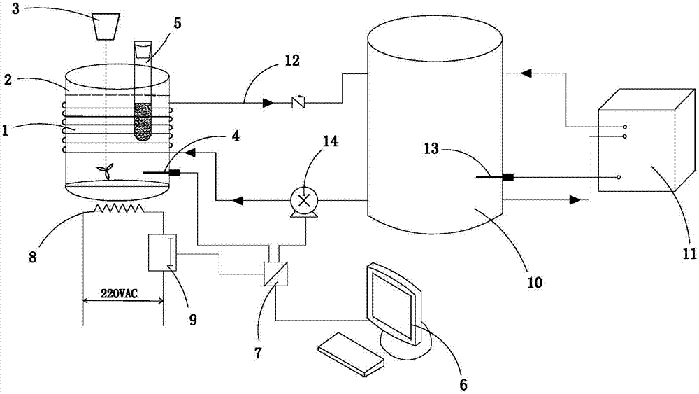
[0013] A phase change material life testing system, its structure is as follows figure 1 Shown, comprise oil bath 1, test tube 5, electric heating device 8, cooling device and computer 6, described oil bath 1 comprises the pan body 2 that is filled with heat conduction medium, is used for stirring described heat conduction medium (as silicone oil, Water, etc.) stirrer 3 and the first temperature sensor 4 for detecting the temperature of the heat transfer medium; the inside of the test tube 5 is filled with a phase change material, and the test tube 5 is located in the pot body 2 and fixed on a fixed bracket Above; the electric heating device 8 is used to heat the heat-conducting medium in the oil bath 1; the cooling device is used to cool the heat-conducting medium in the oil bath 1; the electric hea...


PUM


Abstract

The invention discloses a phase-change material service life testing system. The system comprises an oil bath pan, a test tube, an electric heating apparatus, a cooling device and a computer, the oil bath pan comprises a pan body for containing a heat-conducting medium, a stirrer for stirring a heat-conducting medium, and a first temperature sensor for detecting the heat-conducting medium temperature; the test tube internally contains the phase-change material, and the test tube is in the pan and fixed on a fixing support; the electric heating apparatus is used for heating the heat-conducting medium in the oil bath pan; the cooling apparatus is used for cooling the heat-conducting medium in the oil bath pan; the electric heating apparatus is electrically connected to a temperature controller, the first temperature sensor, the temperature controller and the cooling device are connected to the computer through a communication module, and the computer controls the electric heating apparatus and the cooling device to start and close according to temperature signal fed back by the first temperature sensor. The system has the advantages of reasonable structure, usage safety, high test result accuracy, and good usage effects.

Description

technical field [0001] The invention relates to a service life testing system of a phase change material. Background technique [0002] During the use of phase change materials, due to repeated phase change processes, their structure and function may change. For example, organic phase change materials, due to aging, the material changes its original properties; another example is inorganic hydrated salt phase change materials, due to the inevitable The phase separation tendency of the material will gradually reduce the phase change heat. Therefore, after repeated use, the function of the phase change material will be changed or lost due to the influence of the environment and its own factors. The number of times that the change point drift and the phase change heat undergoes a certain decay is called its life. In the patent document CN1474180A, a method and device for continuously measuring the life of a phase change material are disclosed. The method is to put the phase ch...

Claims


Application Information

Patent Timeline
IPC IPC(8): G01N25/12
CPCG01N25/12
Inventor 凌德力
Owner 浙江省太阳能产品质量检验中心
Why Eureka
Try Eureka