
Stiffened plate shear test loading device

A technology of loading device and stiffened plate, which is applied in the direction of measuring device, using stable shear force to test the strength of materials, instruments, etc., can solve the problem of uneven stress on the reinforcement section

Active Publication Date: 2017-08-11
DALIAN UNIV OF TECH
View PDF7 Cites 2 Cited by
  • Summary
  • Abstract
  • Description
  • Claims
  • Application Information

AI Technical Summary

Problems solved by technology

[0004] In order to solve the above problems, the present invention provides a loading device for shearing experiments on stiffened plates. During the loading process, a shearing force is applied to the middle of the stiffening section around the stiffened plate. The shearing force is uniform around the test piece after passing through a small area. distribution, the stress state of the specimen is very close to the pure shear stress state, which effectively solves the problem of uneven stress on the braced section

Method used


Image

  • Stiffened plate shear test loading device
  • Stiffened plate shear test loading device
  • Stiffened plate shear test loading device

Examples


Embodiment Construction

[0019] The system of the patent of the present invention will be further described below with reference to the accompanying drawings.

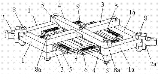
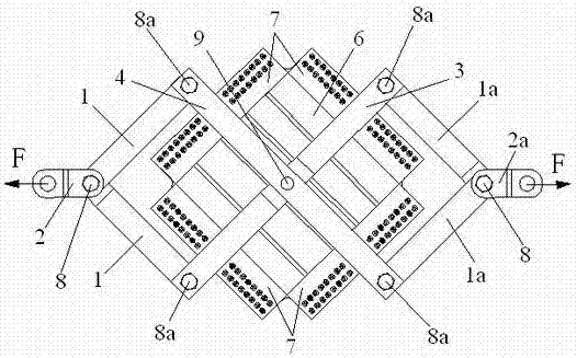
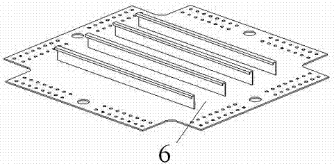
[0020] figure 1 , 2 , 4, 5, 6, 7, and 8 show a structural diagram of a loading device for a stiffened plate shearing experiment. In the figure, this loading device for stiffened plate shear experiment includes two first pull plates 1, two second pull plates 1a, a first loading lug 2, a second loading lug 2a, two first Slide rail 3, two second slide rails 4, four slider structures 5 and eight reinforcement plates 7, dimensions of the first pull plate 1 and the second pull plate 1a, the first slide rail 3 and the second slide rail 4 same.

[0021] The first loading lug 2 is hingedly connected with one end of the two first pull plates 1 by a first pin bolt 8, and the second load lug 2a is connected by another first pin bolt 8 and two second pull plates 1a. One end of the hinge connection. The top of the other ends of the two first pull plate...


PUM


Abstract

A stiffened plate shear test loading device belongs to the technical field of bearing test for aviation stiffened plates. The stiffened plate shear test loading device is characterized in that loading lug forks are hinged to pull plates, the other ends of the pull plates are connected to mutually perpendicular and intersecting slide rails through hinges, the mutually perpendicular and intersecting slide rails are connected in the middle through a pin hinge, and square sliders at two ends of a slider structure mate with slide channels of the slide rails; when force F is loaded to the loading lug forks, component force of the force F is transmitted to the pull plates, the pull plates pull the slide rails to rotate around pins, and inner rail channels of the slide rails apply force parallel to the pull plates to cubes at the top and bottom of the slider structure; during loading, shear force is applied to the middle of peripheral loading segments of a stiffened plate, the shear force is transmitted through a small area and is distributed evenly around a test piece, the stress-bearing state of the test piece is very close to pure shear stress state, and the problem that the loading segments bear stress non-uniformly is solved effectively.

Description

technical field [0001] The invention relates to a loading device for a stiffened plate shearing experiment, which belongs to the technical field of aviation stiffened plate bearing experiments. Background technique [0002] Aerospace stiffened plate structures are often subjected to shear loads during the actual bearing process. Under the action of shear loads, the stiffened plate structures will experience local buckling instability. Studies have shown that the stiffened plate structures still have significant Strong post-buckling capacity. In order to use the structure safely and make full use of the post-buckling capacity of the material, it is often necessary to test the shear capacity of the stiffened plate. [0003] At present, the fixture used to measure the shear bearing capacity of the stiffened plate is mainly based on the picture frame fixture composed of the traditional four-bar linkage mechanism. lower carrying capacity. However, there are two problems when u...

Claims


Application Information

Patent Timeline
Patent Type & Authority Applications(China)
IPC IPC(8): G01N3/24
CPCG01N3/24G01N2203/0025Y02T50/40
Inventor 白瑞祥王大维雷振坤郭振飞田辰光
Owner DALIAN UNIV OF TECH
Learn More