Water-saving type rock or concrete cylindrical sample manufacturing device

A technology for making a device and concrete, applied in the field of geotechnical engineering instruments, can solve the problems such as the uneven side of the cylindrical sample, it is difficult to grasp the depth of the drilling tool, waste materials, manpower, time, etc., so as to improve the production efficiency and expand the Limitations and the effect of improving utilization efficiency

Active Publication Date: 2017-08-11
SHANDONG UNIV OF SCI & TECH
View PDF7 Cites 2 Cited by
  • Summary
  • Abstract
  • Description
  • Claims
  • Application Information

AI Technical Summary

Problems solved by technology

Sampling cannot be achieved if the length of the sample taken exceeds the maximum limit or the diameter of the sample is not the caliber of the existing tool
[0003] Furthermore, in the existing laboratory rock or concrete sampling machines, during the sampling process, with the increase of the drilling depth, the drill pipe tends to swing a little from side to side, which will directly cause the side of the cylindrical sample taken out to be rough. , and sometimes there will be a large dislocation phenomenon, resulting in sampling failure, unable to be used for subsequent sample work, time-consuming, laborious and laborious
[0004] In addition, in the process of drilling and sampling, if there are cracks or joints in the rock, when the tool rotates at high speed, the specimen is easily broken at the joints, which will also lead to sampling failure
[0005] If the height of the required cylindrical sample is less than the depth of the drilling sampler, sometimes it is difficult to grasp the depth of the drilling tool. time
[0006] In addition, the existing stone grinding machine needs to continuously spray water to cool the entire grinding disc surface during grinding, which seriously wastes water resources

Method used


Image

  • Water-saving type rock or concrete cylindrical sample manufacturing device
  • Water-saving type rock or concrete cylindrical sample manufacturing device
  • Water-saving type rock or concrete cylindrical sample manufacturing device

Examples


Embodiment 1

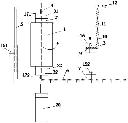
[0031] Such as figure 1 As shown, it includes a frame, which is characterized in that: the frame includes a horizontal guide rail 6, a vertical column 2, a slide bar 5, the vertical column 2 is a hollow structure, and the slide bar 5 includes a first vertical section and a second vertical section. Two cantilever sections, the first vertical section is slidably arranged in the hollow structure of the vertical column 2, and a fixing piece is arranged between the first vertical section and the vertical column 2; the fixing piece It is a first jacking bolt 151 , and the vertical column 2 is provided with a first threaded hole, and the first jacking bolt 151 cooperates with the first threaded hole to withstand and fix the first vertical section.

[0032] The installation space of the sample can be conveniently adjusted by sliding the vertical column 2 and the slide bar 5 up and down, and further, a sample 1 of any height can be produced as required, and the slide bar 5 after adjust...


PUM


Abstract

The invention discloses a water-saving type rock or concrete cylindrical sample manufacturing device. The water-saving type rock or concrete cylindrical sample manufacturing device comprises a frame; the frame is composed of a horizontal guide rail, a vertical stand column and a sliding rod, wherein the vertical stand column and the sliding rod are in sliding fit to adjust a sample mounting space and further can manufacture samples at any height; a sample can be mounted through clamping units of a bearing plate and a rubber plate and driven through a coaxial motor, and a driven grinding mode can be converted into a driving grinding mode; meanwhile, a grinding module which can slide left and right is arranged, and according to the difference of the distance between the grinding module and the center of the sample, cylindrical samples of different diameters can be manufactured; a cooling water pipe can slide along with a vertical slider to save water and energy. The water-saving type rock or concrete cylindrical sample manufacturing device is simple in structure and can complete manufacturing of the cylindrical samples within one step, thereby saving time and labor.

Description

technical field [0001] The invention relates to the field of geotechnical engineering instruments, which belongs to a sample making tool, in particular to a water-saving rock or concrete cylindrical sample making device. Background technique [0002] Existing laboratory rock or concrete sampling machines can only take samples with fixed diameter and limited length. Sampling cannot be achieved if the length of the sample taken exceeds the maximum limit or the diameter of the sample is not the caliber of the existing tool. [0003] Furthermore, in the existing laboratory rock or concrete sampling machines, during the sampling process, with the increase of the drilling depth, the drill pipe tends to swing a little from side to side, which will directly cause the side of the cylindrical sample taken out to be rough. , Sometimes there will be a large dislocation phenomenon, resulting in sampling failure, and the subsequent sample work cannot be carried out, which is time-consumi...

Claims


Application Information

Patent Timeline
IPC IPC(8): G01N1/28
CPCG01N1/286G01N2001/2873
Inventor 王颖胡振华
Owner SHANDONG UNIV OF SCI & TECH
Why Eureka
Try Eureka