
Film thickness measurement system and method

A measurement system and film thickness technology, applied in measurement devices, instruments, optical devices, etc., can solve problems such as inability to realize process monitoring, and achieve the effect of fast measurement speed

Active Publication Date: 2018-07-13
SKYVERSE TECH CO LTD
View PDF3 Cites 0 Cited by
  • Summary
  • Abstract
  • Description
  • Claims
  • Application Information

AI Technical Summary

Problems solved by technology

[0004] There are currently some methods for measuring the film thickness at the bottom of the TSV hole, for example, the analysis of the film thickness at the bottom of the hole by SEM imaging. However, this method is a destructive measurement method that requires cutting the TSV hole for side imaging and can only be used for sampling research, unable to achieve universal process monitoring

Method used


Image

  • Film thickness measurement system and method
  • Film thickness measurement system and method
  • Film thickness measurement system and method

Examples


Embodiment Construction

[0030] In the following detailed description of the preferred embodiment, reference is made to the accompanying drawings which form a part hereof. The accompanying drawings show, by way of example, specific embodiments in which the invention can be practiced. The illustrated embodiments are not intended to be exhaustive of all embodiments in accordance with the invention. It is to be understood that other embodiments may be utilized and structural or logical changes may be made without departing from the scope of the present invention. Accordingly, the following detailed description is not limiting, and the scope of the invention is defined by the appended claims.

[0031] Techniques, methods and devices known to those of ordinary skill in the relevant art may not be discussed in detail, but where appropriate, such techniques, methods and devices should be considered part of the description.

[0032] The inventor found through research that, for the measurement of the TSV ho...


PUM


Abstract

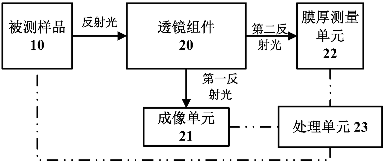
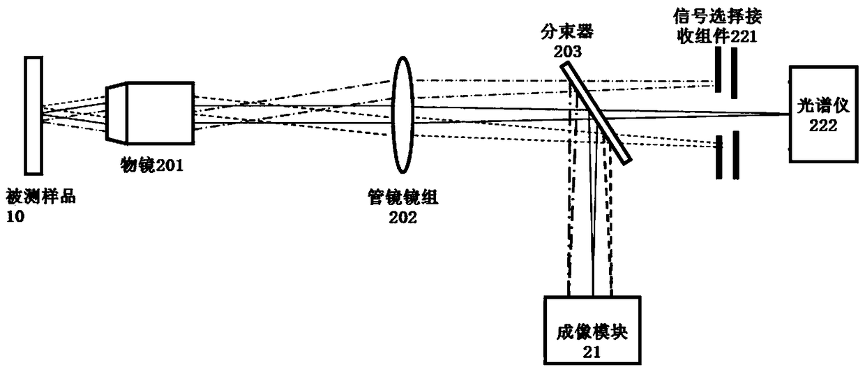
The invention discloses a measurement system, which includes: a lens assembly configured to receive reflected light from a sample to be measured, and to at least divide the reflected light into a first reflected light and a second reflected light; an imaging unit, which is is configured to receive the first reflected light to obtain imaging data of the surface of the tested sample, the imaging data includes distribution information of the tested holes in at least one detection area of ​​the tested sample; the film thickness measurement unit is configured to receive the second reflected light to obtain data of the film thickness of the measured hole at the bottom of the hole; and a processing unit, which is communicatively connected with the imaging unit and the film thickness measurement unit, and is configured to determine the detection path of the measured hole based on the distribution information, and based on the The detection path of the hole is used to enable the film thickness measurement unit to obtain the data of the film thickness of the hole bottom of each measured hole, thereby realizing the measurement of the measured hole in at least one detection area.

Description

technical field [0001] The invention belongs to the field of packaging technology testing, and in particular relates to a measuring device and method for high-precision and non-damaging measurement of film thickness in a measured area. Background technique [0002] With the further development of electronic products towards miniaturization and multi-function, integrated circuits are gradually developing towards high density, light and small size, low energy consumption and system level, and integrated circuit packaging technology has entered the era of high-density packaging. As the traditional packaging method that relies on reducing the feature size to continuously increase the integration level is gradually approaching the limit, three-dimensional packaging technology has become the best choice to continue Moore's Law. Three-dimensional packaging, also known as stacked chip packaging technology, refers to the packaging technology that stacks two or more chips in the same ...

Claims


Application Information

Patent Timeline
Patent Type & Authority Patents(China)
IPC IPC(8): G01B11/06
CPCG01B11/0625G01B2210/56
Inventor 陈鲁
Owner SKYVERSE TECH CO LTD
Learn More