
Novel compressed air energy storage device

A technology of compressed air energy storage and compressed air, which is applied in pump devices, liquid variable capacity machinery, machines/engines, etc. energy and power generation, restricting the development of compressed air energy storage, etc., to achieve the effect of saving materials, realizing utilization efficiency, and not easy to ignite

Active Publication Date: 2017-08-11
HEBEI UNIV OF TECH
View PDF7 Cites 2 Cited by
  • Summary
  • Abstract
  • Description
  • Claims
  • Application Information

AI Technical Summary

Problems solved by technology

However, these compressed air energy storage methods will waste a lot of energy in the form of heat energy in the process of compressing air, and because these compressed air energy storage devices do not have the influence of the clearance volume, the energy conversion efficiency is not ideal , and in the process of energy discharge, it is inevitable that a large amount of energy will be wasted due to the mismatch between power generation and power consumption, which greatly restricts the development of compressed air energy storage
[0003] Chinese patent CN104675464A discloses a multi-stage compressed air energy storage system. This system designs a hierarchical energy storage device to store energy. However, the system is in a theoretical state and is realized by directly connecting multiple compressors in series. In practice, The direct series connection of the compressors in the application will cause the sudden stop of the compressors, and the system does not give the specific pressure relationship of the multi-stage compressed air energy storage, only a step-by-step boosting scheme is given, which cannot be applied in practice , also failed to solve the problem of inconsistency between power consumption and power generation

Method used


Image

  • Novel compressed air energy storage device
  • Novel compressed air energy storage device
  • Novel compressed air energy storage device

Examples


Embodiment 1

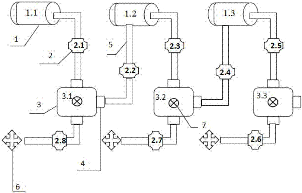
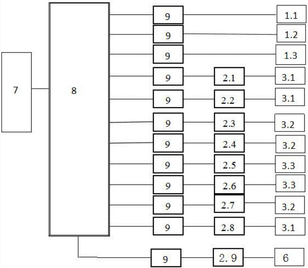
[0036] The novel compressed air energy storage device of this embodiment includes a control system, three energy storage parts and three power generation parts, which are three-stage compression energy storage, and the control system is used to control the energy storage part and the power generation part to perform corresponding actions; the storage The energy part includes an air compressor 1 and an air storage tank 3. The outlet of the air compressor 1 is connected to the inlet of the air storage tank through a high-pressure pipe 5, and the gas outlet of the air storage tank is connected to the inlet of the next-stage air compressor through a high-pressure pipe. The air outlet of the air storage tank communicates with the outside atmosphere through a high-pressure pipe; a solenoid valve 2 is installed on each connected corresponding high-pressure pipe, and a power generation part is installed at the other end of the high-pressure pipe connected to the air outlet of the air st...


PUM


Abstract

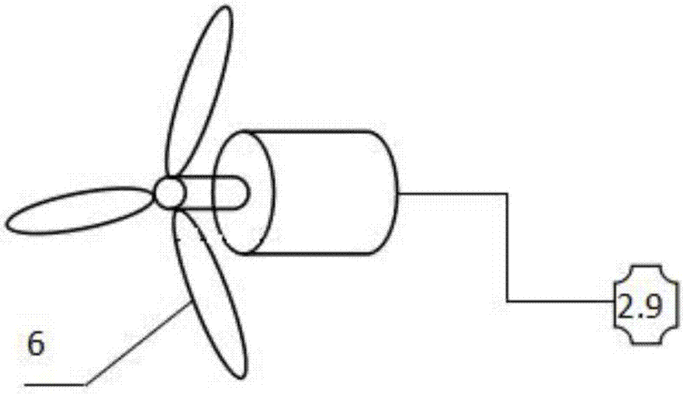
The invention relates to a novel compressed air energy storage device characterized by comprising a control system, N energy storage parts and N generating parts; N is larger than or equal to 2 and is N-level compression energy storage; the control system is used for controlling the energy storage parts and the generating parts to perform corresponding actions; each energy storage part comprises an air compressor and an air storage tank; an outlet of the air compressor is connected with an inlet of the air storage tank by a high-pressure pipe; an air outlet of the air storage tank is connected with an inlet of the next-level air compressor by a high-pressure pipe; an exhaust outlet of the air storage tank communicates with the external air by a high-pressure pipe; each connected corresponding high-pressure pipe is provided with an electromagnetic valve; the other end of the high-pressure pipe connected with the exhaust outlet of the air storage tank is provided with each generating part; the first-level air compressor provides air source power and converts superfluous power generated by a power grid during the low peak of power utilization into internal energy of a gas; an air outlet of the Nth-level air storage tank is sealed; and each generating part comprises a wind driven generator and an electromagnetic valve for controlling the wind driven generator.

Description

technical field [0001] The invention relates to the technical field of energy storage and energy discharge, in particular to a novel compressed air energy storage device. Background technique [0002] Since Stal Laval proposed the use of compressed air energy storage in 1949, scholars at home and abroad have conducted a lot of research. At present, two large traditional compressed air energy storage power stations have been put into operation in the world. Compressed air energy storage refers to the energy storage method that uses electric energy to compress air during the low load period of the grid, and releases the compressed air to drive the steam turbine to generate electricity during the peak load period of the grid. The main forms are traditional compressed air energy storage system, compressed air energy storage system with heat storage device, and liquid-gas compressed energy storage system. However, these compressed air energy storage methods will waste a lot of ...

Claims


Application Information

Patent Timeline
IPC IPC(8): F04B41/02F01D15/10
CPCF01D15/10F04B41/02Y02E60/16
Inventor 张家安王佶宣张健魏建雄刘熙方鑫宇李京艺李正
Owner HEBEI UNIV OF TECH
Learn More