Induction type lifting sound barrier system and working method thereof

A working method and sound barrier technology, applied in construction, noise absorption devices, etc., can solve the problems of not being well integrated into the environment, short service life of the sound barrier, and affecting the vision of residents along the line, so as to achieve environmental friendliness and harmony, reduce Damage probability, fatigue damage reduction effect

Active Publication Date: 2017-08-11
EAST CHINA JIAOTONG UNIVERSITY
View PDF5 Cites 1 Cited by
  • Summary
  • Abstract
  • Description
  • Claims
  • Application Information

AI Technical Summary

Problems solved by technology

However, with the wide application of sound barriers and the rapid development of high-speed railways, the sound barriers have a short service life, affect the vision of residents along the line, and cannot be well integrated into the environment.
Under the long-term train wind and natural wind load, the sound barrier is prone to fatigue damage, which can lead to train safety accidents in severe cases

Method used


Image

  • Induction type lifting sound barrier system and working method thereof
  • Induction type lifting sound barrier system and working method thereof
  • Induction type lifting sound barrier system and working method thereof

Examples


Embodiment 1

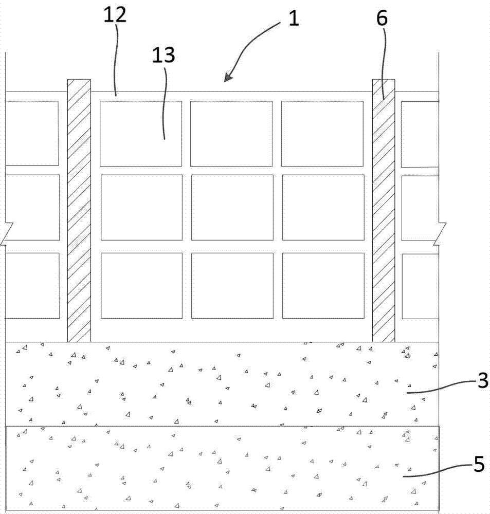
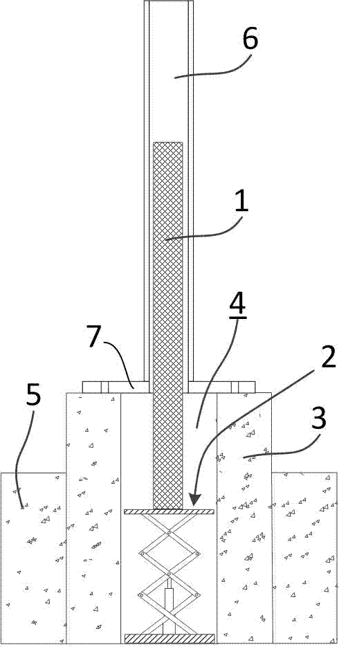
[0033] Embodiment 1: as figure 1 , 2 As shown, this embodiment specifically relates to an inductive lifting sound barrier system, which includes a sound barrier plate 1, a lifting mechanism 2, and a base 3; the base 3 is provided with an accommodating groove 4 for accommodating the sound barrier plate 1; The mechanism 2 is arranged between the base 3 and the sound barrier panel 1, and is used to drive the sound barrier panel 1 up and down.

[0034] Such as figure 2 As shown, the base 3 is arranged on the side of the railway, and the bottom of the base 3 is connected with the lower foundation 5; the lower foundation 5 and the base 3 are all made of concrete pouring; The shape is adapted to the shape of the sound barrier baffle 1 .

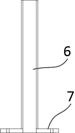
[0035] Such as figure 1 , 3 , 4, the two sides of the top opening of the accommodation groove 4 are respectively provided with a vertical guide rail 6, and the vertical guide rail 6 is provided with a vertical groove matching with the edge of ...

Embodiment 2

[0040] Embodiment 2: This embodiment specifically relates to the working method of the inductive lifting sound barrier system in Embodiment 1. This method includes the following steps:

[0041] Such as figure 1 , 10 As shown, the sound barrier plate 1, the base 3 and the lifting mechanism 2 are arranged on both sides of the railway line to form a sound barrier area; and displacement sensors 21 are respectively arranged in front and rear of the sound barrier plate 1, two displacement sensors 21 and the sound barrier The distance between the plate 1 is 200m, and it is specifically fixed at the position between the bottom of the rail and the track plate.

[0042] Such as figure 2 , 10 As shown, when the train enters the sound barrier area, when the wheels of the train pass through the installation position of the first displacement sensor 21, the train causes the rail to generate a large vertical displacement instantaneously. At this time, the first displacement sensor 21 wil...


PUM


Abstract

The invention discloses an induction type lifting sound barrier system and a working method thereof. The lifting sound barrier system comprises a sound barrier board, a lifting mechanism and a base; a containing groove which is used for containing the sound barrier board is formed in the base; the lifting mechanism is arranged between the base and the sound barrier board and used for driving the sound barrier board to ascend and descend. The induction type lifting sound barrier system has the advantages that compared with a traditional sound barrier, the induction type lifting sound barrier can allow the natural wind to pass through a railway line area smoothly in a non-working state, the influence of external environmental factors such as a natural wind load and aging caused by sunshine can be avoided, accordingly, the damage probability of the sound barrier is lowered, and the cost of late period maintenance and replacement is greatly reduced.

Description

technical field [0001] The invention belongs to the technical field of railway engineering, and in particular relates to an inductive lifting sound barrier system and a working method thereof. Background technique [0002] The environmental noise problem caused by high-speed railway, intercity railway and urban rail transit is one of the key issues restricting the healthy and rapid development of rail transit. [0003] Traditional sound barriers are designed to solve the problem of railway noise pollution. The noise reduction principle of the sound barrier is to insert a sound barrier between the sound source and the sound receiver. During the propagation of the sound wave, when it encounters the sound barrier, three phenomena will occur: reflection, transmission and diffraction, so that the direct sound can be prevented. Propagation, and make the propagation of sound waves produce a significant additional attenuation, so as to achieve the purpose of noise reduction. After...

Claims


Application Information

Patent Timeline
Patent Type & Authority Applications(China)
IPC IPC(8): E01F8/00
CPCE01F8/0023
Inventor 罗锟雷晓燕冯青松黄大维
Owner EAST CHINA JIAOTONG UNIVERSITY
Why Eureka
Try Eureka