
High-efficient polishing machine

A polishing machine, high-efficiency technology, used in grinding/polishing equipment, grinding/polishing safety devices, grinding machines, etc. It is easy to promote and use, reduce manual cleaning, and avoid potential safety hazards.

Inactive Publication Date: 2017-08-11
MAANSHAN NIUZE TECH SERVICE
View PDF0 Cites 9 Cited by
  • Summary
  • Abstract
  • Description
  • Claims
  • Application Information

AI Technical Summary

Problems solved by technology

[0002] The grinder is a manual electric tool used to polish the surface of the object. The key to the operation of the grinder is to try to get the maximum polishing rate so that the damaged layer generated during the grinding can be removed as soon as possible, and at the same time, the polishing The damaged layer will not affect the final observed tissue, but in the actual work of the polisher, the Buffon debris generated by the grinding will adhere to the polished place, which is not conducive to the observation and treatment of the polished place, so that Cao Cheng's polished Repeated cleaning reduces work efficiency. Due to the high frequency of use of the grinder, it is naturally inevitable to avoid internal heating caused by long-term use. The motor and internal components work at high temperatures for a long time, and cannot get timely and effective heat dissipation. It is easy to burn out the motor and internal components. In addition, when the existing grinder grinds hard objects, the grinder will vibrate violently, and the hands of the operator will often be numb due to the vibration. Due to the working environment and processing angle, As a result, the light is blocked, and the processing cannot be seen clearly, which affects work efficiency

Method used


Image

  • High-efficient polishing machine
  • High-efficient polishing machine

Examples


Embodiment Construction

[0014] The following will clearly and completely describe the technical solutions in the embodiments of the present invention with reference to the accompanying drawings in the embodiments of the present invention. Obviously, the described embodiments are only some, not all, embodiments of the present invention. Based on the embodiments of the present invention, all other embodiments obtained by persons of ordinary skill in the art without making creative efforts belong to the protection scope of the present invention.

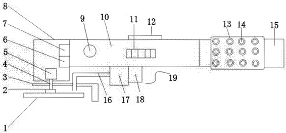
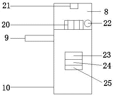
[0015] see Figure 1-2 , the present invention provides a technical solution: a high-efficiency polishing machine, including a body 10, the front end of the body 10 is fixedly connected to the machine head 8, the rear end of the body 10 is connected to a handle 15, and the front surface of the body 10 is provided with a first Cooling holes 11 increase the heat dissipation effect. An auxiliary handle 9 is provided on the left side of the first cooling hole 11, ...


PUM


Abstract

The invention discloses a high-efficiency polishing machine, which mainly includes a fuselage, the front end of the fuselage is fixedly connected to the machine head, the rear end of the fuselage is connected to a handle, and the front surface of the fuselage is provided with a first cooling hole. An auxiliary handle is provided on the left side of the first heat dissipation hole, a second heat dissipation hole is provided on the top of the machine head, a lighting lamp is provided at the front end of the top of the machine head, a motor is provided inside the machine head, and the bottom of the machine head is fixed Connect the protective cover, the bottom of the motor is connected to the vertical shaft, and the vertical shaft passes through the bottom of the head and the bottom of the protective cover in turn to connect to the rotating shaft, one end of the rotating shaft is fixedly connected to the grinding wheel, and the top of the fuselage is provided with a switch assembly. There is a dust suction device at the bottom of the fuselage. The invention has a simple mechanism and a novel design, and the scraps generated during the operation can be recovered, ensuring that there is no attachment on the polished surface of the object, reducing manual cleaning and improving work efficiency.

Description

technical field [0001] The invention relates to the technical field of electric tools, in particular to a high-efficiency grinder. Background technique [0002] The grinder is a manual electric tool used to polish the surface of the object. The key to the operation of the grinder is to try to get the maximum polishing rate so that the damaged layer produced during the grinding can be removed as soon as possible, and at the same time, the polishing The damaged layer will not affect the final observed tissue, but in the actual work of the polishing machine, the Buffon debris generated by the grinding will adhere to the polished place, which is not conducive to the observation and treatment of the polished place, so that Cao Cheng's polished Repeated cleaning reduces the work efficiency. Due to the high frequency of use of the grinder, it is natural that the internal heating phenomenon caused by long-term use cannot be avoided. The motor and internal components work at high tem...

Claims


Application Information

Patent Timeline
Patent Type & Authority Applications(China)
IPC IPC(8): B24B23/02B24B55/10B24B55/12
CPCB24B23/02B24B55/102B24B55/12
Inventor 施享
Owner MAANSHAN NIUZE TECH SERVICE
Learn More