
Apparatus and method for fiber optic bundle coupling

A fiber bundle and grating technology, applied in the field of optical communication, can solve problems such as coupling efficiency loss and achieve high coupling efficiency

Active Publication Date: 2018-12-14
HUAWEI TECH CO LTD
View PDF3 Cites 0 Cited by
  • Summary
  • Abstract
  • Description
  • Claims
  • Application Information

AI Technical Summary

Problems solved by technology

[0003] The grating coupler is the key device for the input and output of the silicon-based PIC chip. The signal light needs to be coupled from the fiber bundle to the silicon-based PIC chip in the grating coupler through the waveguide bundle. However, the signal light is reflected to the silicon-based PIC chip by mirror reflection. When in a PIC chip, due to the divergence of light, the mode spot size reflected into the silicon-based PIC chip is mismatched with the size of the mode spot in the silicon-based PIC chip. This mismatch of mode spots will lead to a huge loss of coupling efficiency

Method used


Image

  • Apparatus and method for fiber optic bundle coupling
  • Apparatus and method for fiber optic bundle coupling
  • Apparatus and method for fiber optic bundle coupling

Examples


Embodiment Construction

[0039] The following will clearly and completely describe the technical solutions in the embodiments of the present invention with reference to the drawings in the embodiments of the present invention. Obviously, the described embodiments are part of the embodiments of the present invention, not all of them. Based on the embodiments of the present invention, all other embodiments obtained by persons of ordinary skill in the art without making creative efforts shall fall within the protection scope of the present invention.

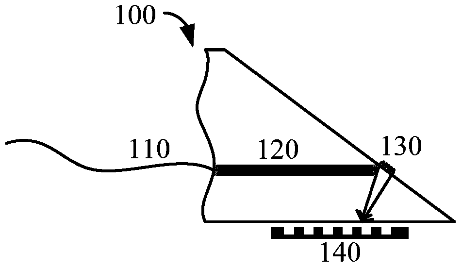
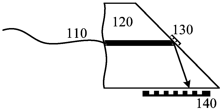
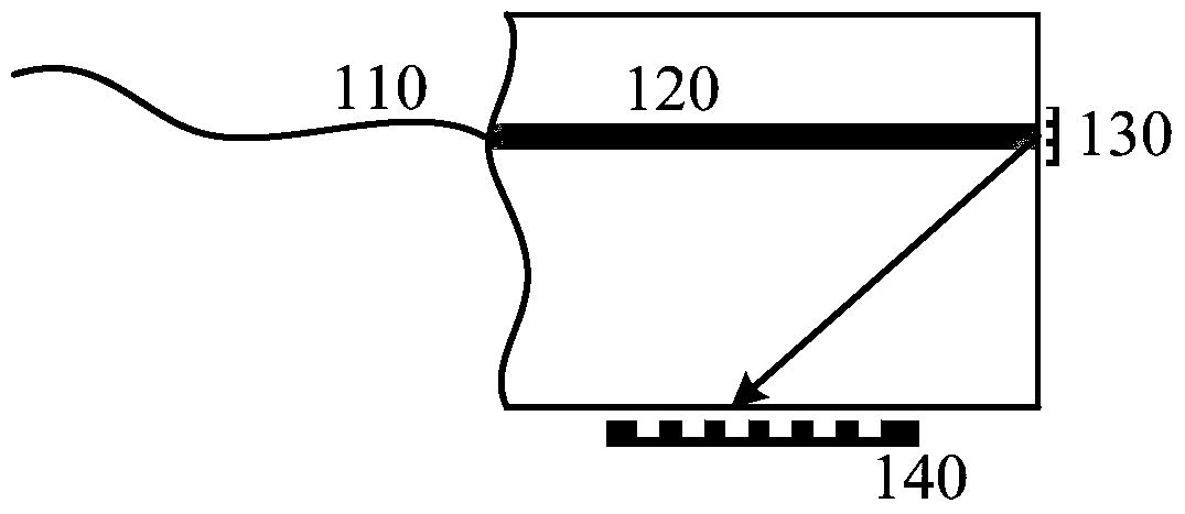
[0040] figure 1 A schematic side view of a device 100 for fiber bundle coupling according to an embodiment of the present invention is shown. Such as figure 1 As shown, the device 100 includes: at least one optical fiber bundle 110, at least one waveguide bundle 120, at least one mode spot shaping unit group 130 and at least one target grating group 140, and each optical fiber bundle in the at least one optical fiber bundle 110 includes at least A fiber ...


PUM


Abstract

The invention discloses a device and a method for coupling optical fiber bundles, wherein optical coupling efficiency can be improved. The device comprises at least one optical fiber bundle, at least one waveguide bundle, at least one speckle shaping unit set and at least one target grating set. Each optical fiber bundle comprises at least one fiber core. Each waveguide bundle comprises at least one optical waveguide. Each speckle shaping unit set comprises at least one speckle shaping unit. Each target optical grating set comprises at least one target grating, wherein the first optical waveguide is used for receiving first signal light which is input from the first fiber core. The first speckle shaping unit is used for receiving the first signal light which is output through the first optical waveguide and performing speckle shaping processing on the speckle that corresponds with the first signal light so that the first signal light is transmitted to the first target grating. After speckle shaping processing is performed on the first signal light, a first speckle which is reflected to the first target grating is smaller than a second speckle that is reflected to the first target grating without speckle shaping processing.

Description

technical field [0001] Embodiments of the present invention relate to the technical field of optical communication, and more specifically, relate to a device and method for optical fiber bundle coupling. Background technique [0002] With the development of high-speed, high-capacity optical communication technology, a key technology in optical integrated devices is to realize the effective coupling of optical waveguides and optical fibers. For example, the optical waveguide may be a silicon-based Photonic Integrated Circuit ("PIC" for short) chip. [0003] The grating coupler is a key device for the input and output of the silicon-based PIC chip. The signal light needs to be coupled from the fiber bundle to the silicon-based PIC chip in the grating coupler through the waveguide bundle. However, the signal light is reflected to the silicon-based PIC chip by mirror reflection. When in the PIC chip, due to the divergence of light, the mode spot size reflected into the silicon-...

Claims


Application Information

Patent Timeline
Patent Type & Authority Patents(China)
IPC IPC(8): G02B6/38G02B6/40G02B27/09
CPCG02B6/38G02B6/40G02B27/0944
Inventor 李明涂鑫赵飞
Owner HUAWEI TECH CO LTD
Learn More