
Fairing clamping tool

A fairing and clamping technology, applied in the field of machining, can solve the problems of deformation and the difficulty of clamping the fairing, and achieve the effect of reducing the deformation and solving the difficulty of clamping

Active Publication Date: 2017-08-04
WUHAN MARINE MACHINERY PLANT
View PDF7 Cites 10 Cited by
  • Summary
  • Abstract
  • Description
  • Claims
  • Application Information

AI Technical Summary

Problems solved by technology

[0005] In order to solve the problem that the fairing is difficult to clamp and easy to deform during the clamping process, the embodiment of the present invention provides a fairing clamping tool

Method used


Image

  • Fairing clamping tool
  • Fairing clamping tool
  • Fairing clamping tool

Examples


Embodiment Construction

[0030] In order to make the object, technical solution and advantages of the present invention clearer, the implementation manner of the present invention will be further described in detail below in conjunction with the accompanying drawings.

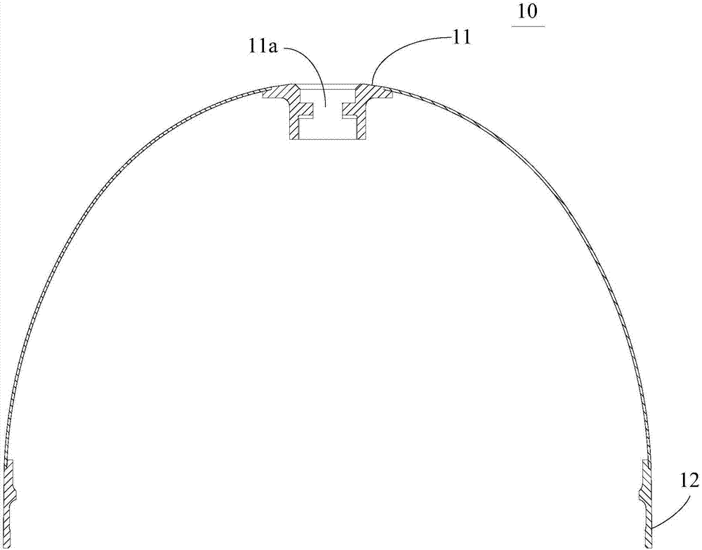
[0031] In order to understand the present invention better, combine below figure 1 The structure of the fairing will be briefly described. figure 1 is a structural schematic diagram of a fairing, such as figure 1 As shown, the fairing is in the shape of a parabola. The fairing has a small end 11 and a large end 12. The small end 11 is provided with a central hole 11a extending along the axial direction of the fairing. The central hole 11a is used to install other parts, and the center There may also be an inner flange on the inner wall of the hole 11a.

[0032] The fairing belongs to a thin shell part, and the wall thickness of the thin shell part is very small compared to the length, width and height. For example, in an existing fai...


PUM


Abstract

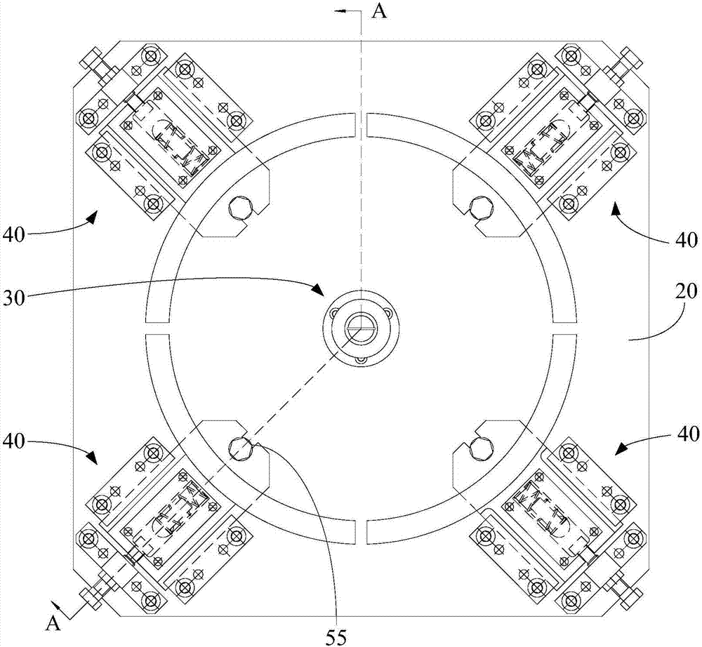
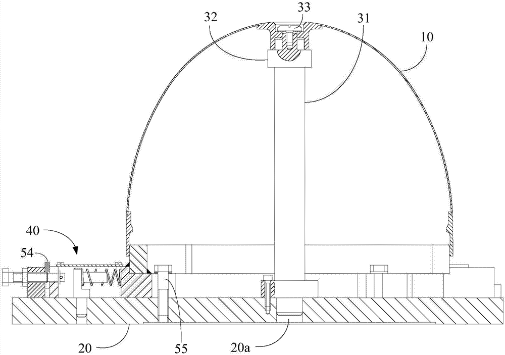
The invention discloses a fairing clamping tool, and belongs to the field of machining. The clamping tool comprises a bottom plate, a centering assembly and a plurality of tightening assemblies. The centering assembly comprises a centering shaft, the centering shaft is perpendicularly arranged on the bottom plate, and the tightening assemblies are arranged on the bottom plate in the circumferential direction with the centering shaft as the center. Each tightening assembly comprises a sliding block, a tightening block and a locking mechanism. The sliding blocks can be arranged on the bottom plate in the manner of sliding in the radial direction of the centering shaft. The tightening blocks are arranged on the sliding blocks, and the surfaces, away from the centering shaft, of the tightening blocks are arc faces. The orthographic projection of the arc faces on the bottom plate is an arc line, and the radius of the arc line is identical to the inner diameter of the large end of a fairing to be clamped. The locking mechanisms are used for locking the sliding blocks, and the sliding blocks and the bottom plate are relatively static. The tightening blocks and the inner wall of the large end of the fairing are in contact by moving the sliding blocks, then the sliding blocks are locked through the locking mechanisms, the sliding blocks cannot slide, and therefore the large end of the fairing can be located.

Description

technical field [0001] The invention relates to the field of mechanical processing, in particular to a fairing clamping tool. Background technique [0002] A fairing is a thin shell part used to reduce fluid resistance, and is usually arranged on the head of an aircraft or aircraft. [0003] The fairing is usually in the shape of a parabola. The fairing has a small end and a large end. The axial section of the fairing decreases gradually along the direction from the large end to the small end. The small end is provided with a central hole extending along the axial direction of the fairing. The center hole is for mounting other parts. [0004] Since there is no flange for connection on the fairing, the flange cannot be used for positioning and clamping like other parts in the process of clamping the fairing, which makes it difficult to clamp the fairing. It is a thin-shell part, and the wall thickness of the thin-shell part is very small compared to the length, width and he...

Claims


Application Information

Patent Timeline
Patent Type & Authority Applications(China)
IPC IPC(8): B23Q3/06
CPCB23Q3/065
Inventor 黄若峰马向红薛小星杨家军张实展刘风郭学杰
Owner WUHAN MARINE MACHINERY PLANT
Learn More