
Vena cava filter of multilayer filtration

A multi-layer filtration and vena cava technology, applied in the field of medical devices, can solve problems such as inaccurate release process, easy damage to blood vessel walls, and bouncing positioning, so as to prevent tilting, prolong recovery time, and avoid sticking to the wall

Active Publication Date: 2017-08-04
HANGZHOU WEIQIANG MEDICAL TECH CO LTD
View PDF11 Cites 4 Cited by
  • Summary
  • Abstract
  • Description
  • Claims
  • Application Information

AI Technical Summary

Problems solved by technology

[0004] The technical problem to be solved by the present invention is to solve the defects that the double-layer filter in the prior art is released through the femoral vein and is prone to bounce and inaccurate positioning, resulting in uncontrollable release process and easy damage to the vessel wall. A two-way controllable release, which can be implanted and recovered through the femoral vein, and can be implanted and recovered through the jugular vein, and has better self-centering, and is more easily captured and recovered.

Method used


Image

  • Vena cava filter of multilayer filtration
  • Vena cava filter of multilayer filtration
  • Vena cava filter of multilayer filtration

Examples


Embodiment 1

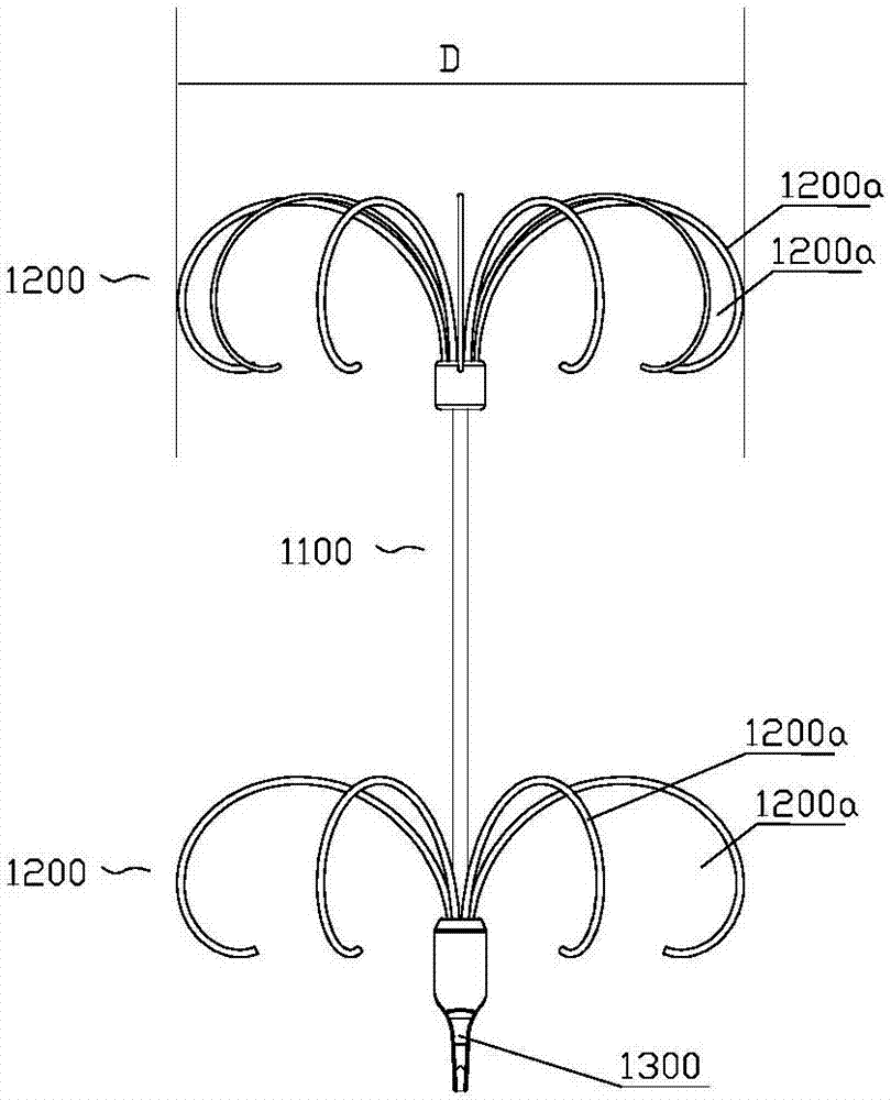
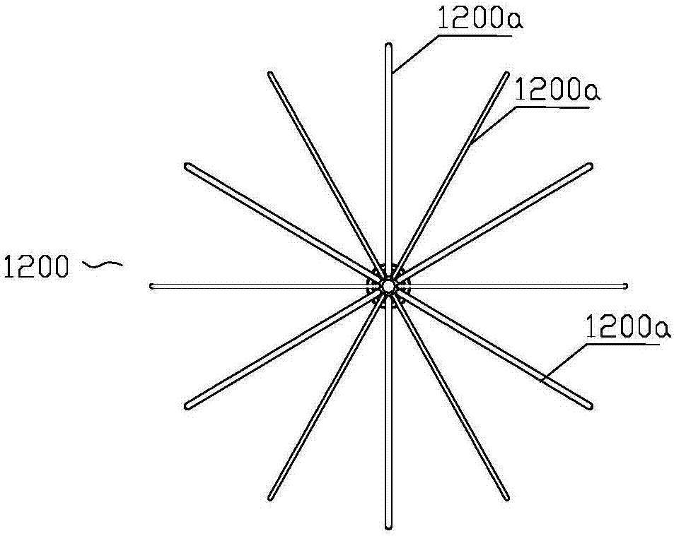
[0052] Example 1, such as Figure 2-9 As shown, a multi-layer filtering vena cava filter, at least two filter elements 1200 arranged at intervals in the axial direction, a connecting rod 1100 for connecting the two filter elements 1200 is provided between adjacent filter elements 1200; each The filter elements 1200 extend from the center to the outside in one direction in the axial direction, and gradually turn over and roll in reverse, and are respectively supported on the inner wall of the blood vessel at points.

[0053] The filter of the present invention includes at least three parts: two filter elements 1200 , and a connecting rod 1100 connecting the two filter elements 1200 . The number of filter elements 1200 can also be increased by 1-3 according to the actual situation, and a plurality of filter elements 1200 are connected by connecting rods 1100. All filter elements 1200 of the present invention have the same basic structure. There are differences in the number and...

Embodiment 2

[0067] Example 2, such as Figure 10 As shown, this embodiment is based on Embodiment 1, the filter further includes a support 1400 for supporting on the inner wall of the blood vessel, and the support 1400 gradually extends outward in one axial direction from the connecting rod 1100 , The end of the support member 1400 is parallel to the central axis or folded towards the central axis. The supporting member 1400 is distributed axially symmetrically around the central axis by auxiliary supporting rods, and the number of auxiliary supporting rods is preferably set at 3-6. Other structures are the same as those in Embodiment 1, and will not be repeated here.

Embodiment 3

[0068] Example 3, such as Figure 11-15 As shown, in this embodiment, on the basis of Embodiment 1, the connecting rod 1100 can be bent and positioned to conform to the bending of the blood vessel. There are many specific implementation methods for the bending of the connecting rod 1100:


PUM


Abstract

The invention discloses a vena cava filter of multilayer filtration. The vena cava filter comprises at least two filter parts arranged at intervals in the axial direction, and a connecting rod used for making the two filter parts connected is arranged between adjacent filter parts; each filter part extends from the center to the outer sides of far ends, is everted and curled in the reverse direction step by step, and supported on the inner wall of a blood vessel in a point mode respectively. Aiming at the defects that the releasing process is uncontrollable and the blood vessel wall is likely to be damaged due to the problems that, in the prior art, filters are released through a femoral vein, bounce is likely to occur and positioning is inaccurate, the vena cava filter of multilayer filtration which can be controllably released in dual directions is provided; not only can the vena cava filter of multilayer filtration be implanted and recycled through a femoral vein and a jugular vein, but the vena cava filter of multilayer filtration has better self-centrality and is easier to capture and recycle.

Description

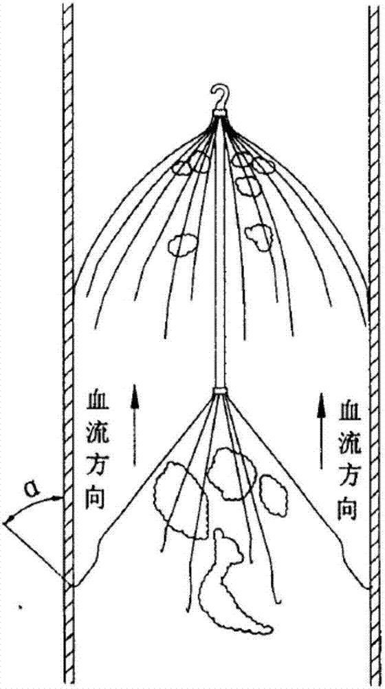
technical field [0001] The invention belongs to the technical field of medical devices, and relates to a filter, in particular to a multi-layer filtering vena cava filter. Background technique [0002] Pulmonary embolism (PE) is a common health problem and an important cause of death in all age groups. Most pulmonary embolisms are caused by deep vein thrombosis (DVT) in the lower extremities or in the pelvis, in which blood clots can migrate through the veins back to the heart and into the lungs, losing blood and oxygen to part of the lungs supply leading to pulmonary infarction. [0003] like figure 1 As shown, in the prior art, there is a vena cava filter with multi-layer filtration of a double-layer conical filter mesh structure. The disadvantage of this filter is that when the filter is released through the thigh, the release process is uncontrollable. After the filter is pushed out of the sheath, The filter screen bounces off quickly and bounces, which makes the posi...

Claims


Application Information

Patent Timeline
Patent Type & Authority Applications(China)
IPC IPC(8): A61F2/01
Inventor 赵珺张庭超李阳
Owner HANGZHOU WEIQIANG MEDICAL TECH CO LTD
Learn More