Three-component valve
A three-component, valve body technology, applied in coatings, devices for coating liquid on the surface, etc., can solve the problems of easy wear of sealing ring pads, slow dispensing speed, inconvenience, etc., so that the sealing structure is not easy to damage, Diversified functions and clean glue breaking effect
- Summary
- Abstract
- Description
- Claims
- Application Information
AI Technical Summary
Problems solved by technology
Method used
Image

Examples
Embodiment 1
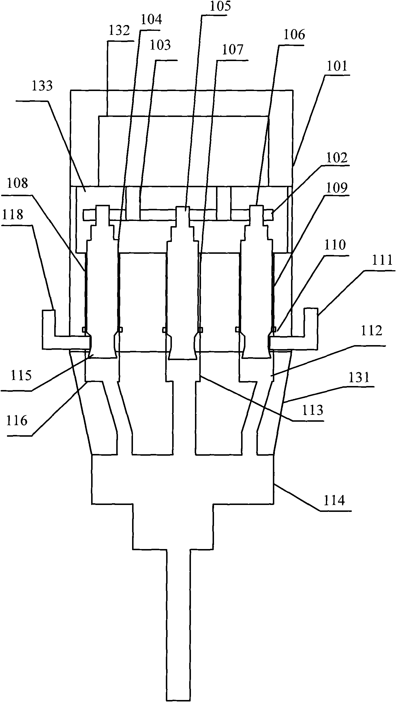
[0033] Such as figure 1 , figure 2 As shown, a three-component valve, a valve body includes an upper valve body 101 and a lower valve body 131; the upper valve body 101 includes an upper valve body shell and a driving mechanism arranged in the upper valve body shell 132;
[0034] A cavity 133 is set in the upper part of the lower valve body 131, and at least three piston passages, namely the first piston passage 108, the second piston passage 107, and the third piston passage 109, are arranged in parallel at the bottom of the cavity 133. A piston passage 108 is the first piston 104, is arranged on the second piston passage 107 and is the second piston 105, is arranged on the third piston passage 109 and is the third piston 106; the afterbody of each piston passage is provided with a glue outlet, that is, The end section of the first piston passage 108 is provided with a first glue outlet hole 116, the end section of the second piston passage 107 is provided with a second gl...
Embodiment 2
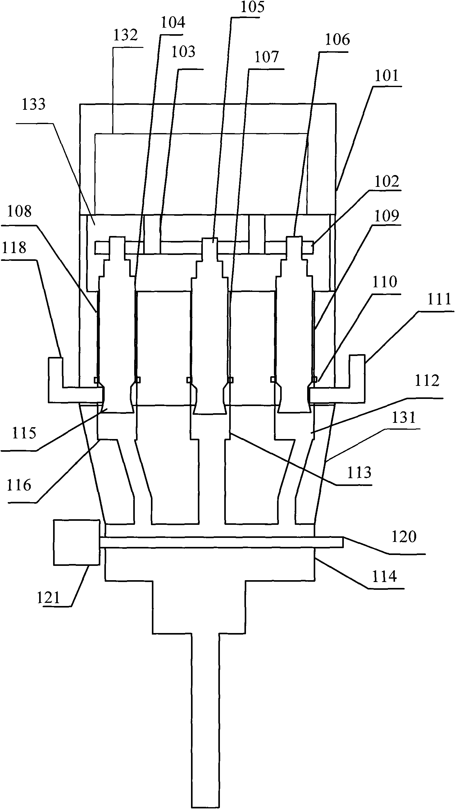
[0038] Such as figure 1 , figure 2 , image 3As shown, when the driving mechanism in the casing of the upper valve body 101 is a motor driving device 132B, the motor driving device 132B includes, a motor 22B is arranged in the upper cavity 28B, and the motor 22B and the transmission The heads of the shaft 4B are connected, the middle part of the transmission shaft 4B is arranged in the transmission shaft channel 20B, the tail part of the transmission shaft 4B is arranged at the upper part inside the lower cavity 29, and in the cavity 133 Inside, the top of each piston arranged in parallel is fixed on the same connecting plate 102, and a connecting device 103 is arranged on the connecting plate 102, and the connecting device is at least connected by a transmission shaft 8B;
[0039] In the process of daily use, the three-component valve is usually installed on the fixed end of the glue dispenser or manipulator or robot to complete the glue spraying process. First, adjust the...
Embodiment 3
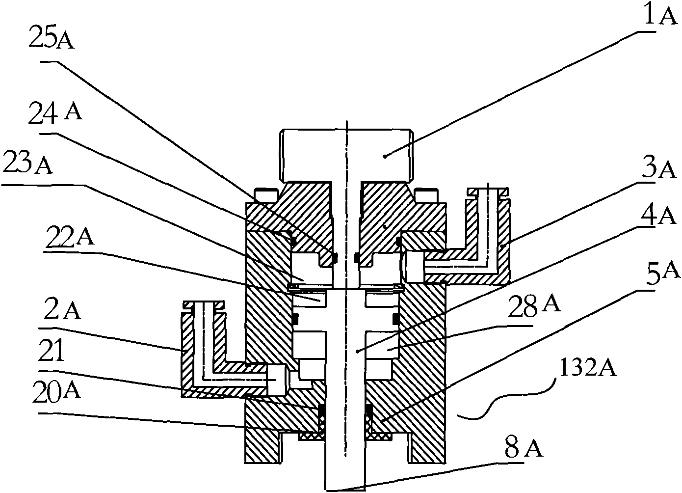
[0045] Such as figure 1 , figure 2 , Figure 4 As shown, when the driving mechanism in the shell of the upper valve body 101 is a pneumatic driving device 132A; the pneumatic driving device 132A includes an adjustment knob 1A arranged on the head of the upper valve body, and the upper valve body A cylinder and a transmission shaft are arranged in the body 101, the head of the transmission shaft is a cross-shaped head, the cross-shaped head is arranged in the cylinder, and the cross-shaped head is connected with the adjustment knob , the middle part of the transmission shaft is arranged in the transmission shaft channel, and the tail of the transmission shaft is connected to the connecting plate through a connecting device;
[0046] The cross-shaped head is arranged in the cylinder 22A, the cross-shaped head is connected with the adjustment knob 1A, the middle part of the transmission shaft 8A is arranged in the first channel 20A, and the transmission The tail portion of th...
PUM
 Abstract
Description
Claims
Application Information
 - R&D
- Intellectual Property
- Life Sciences
- Materials
- Tech Scout
- Unparalleled Data Quality
- Higher Quality Content
- 60% Fewer Hallucinations
Browse by: Latest US Patents, China's latest patents, Technical Efficacy Thesaurus, Application Domain, Technology Topic, Popular Technical Reports.
© 2025 PatSnap. All rights reserved.Legal|Privacy policy|Modern Slavery Act Transparency Statement|Sitemap|About US| Contact US: help@patsnap.com