Electrostatic encoder

An encoder, electrostatic technology, applied in the field of electrostatic encoder, can solve the problem of voltage deviation to either positive or negative

Active Publication Date: 2017-08-01
ORIENTAL MOTOR
View PDF10 Cites 0 Cited by
  • Summary
  • Abstract
  • Description
  • Claims
  • Application Information

AI Technical Summary

Problems solved by technology

As a result, the amplitude-modulated voltage of the output signal from th

Method used


Image

  • Electrostatic encoder
  • Electrostatic encoder
  • Electrostatic encoder

Examples


Embodiment Construction

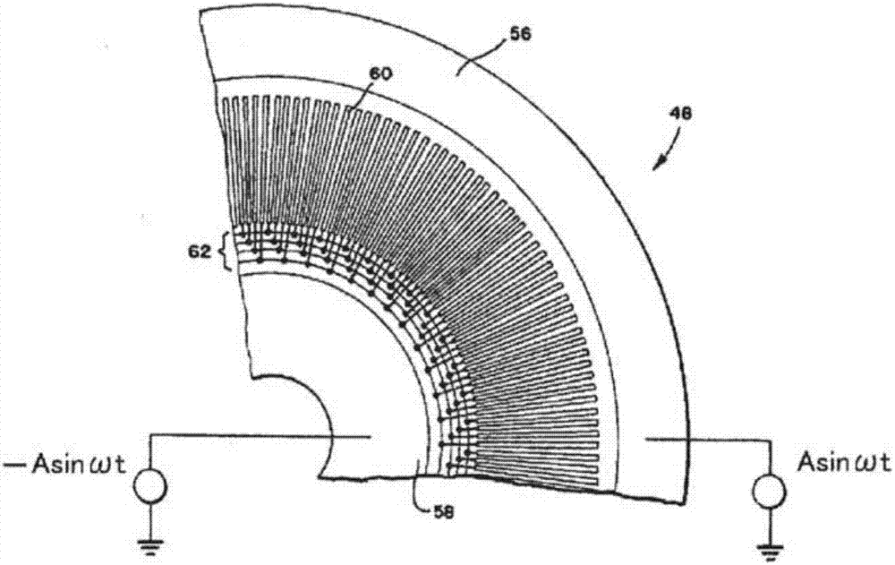
[0029] Figure 4 It is a diagram explaining the basic principle of obtaining the output signal of the rotary electrostatic encoder 40 according to the first embodiment of the present invention. In the electrostatic encoder 40 , electrode surfaces formed on a stator 41 and a rotor 42 are arranged to face each other, and the rotor 42 is rotatably coupled to a center shaft 43 . In the stator 41 , detection electrodes 44 a to 44 d and transmission electrodes 45 a to 45 d are arranged radially from a central axis 46 . The detection electrodes 44 a to 44 d and the transmission electrodes 45 a to 45 d are arranged alternately and at regular intervals along the circumferential direction of the stator 41 . In the rotor 42 , the relay electrodes 47 a to 47 e are arranged at equal intervals in a radial shape from the central axis 43 . The stator 41 and the rotor 42 are made of, for example, a printed substrate of epoxy glass substrate with a diameter of 40 millimeters and a thickness o...


PUM


Abstract

Provided is an electrostatic encoder (40) that detects the rotation angle of a rotor with high accuracy on the basis of a change in electrostatic capacitance between electrodes disposed in a stator (41) and a rotor (42). In this electrostatic encoder, detection electrodes (44a-44d) and transmission electrodes (45a-45d), which are disposed in the stator (41), are alternately disposed in a circumferential direction. Due to the transmission electrodes and the detection electrodes being alternately disposed, detection signals (phase A, phase B), which are amplitude modulated on the basis of rotation of the rotor (42) and have a phase difference of 90 degrees, are output from adjacent detection electrodes. The detection signals having a phase difference of 90 degrees are demodulated and modulated signals (V1, V2) are generated. The rotation angle of the rotor is obtained by applying resolver digital (RD) conversion processing to the modulated signals. Since the transmission electrodes and the detection electrodes are alternately disposed, deviation of the displacements of the modulated signals can be suppressed and the number of detection electrodes can be reduced, and the electrostatic encoder can be reduced in size.

Description

technical field [0001] The present invention relates to an electrostatic encoder, and more specifically, to an arrangement of electrodes formed on a stator and a rotor of the electrostatic encoder. Background technique [0002] Such as figure 1 As shown, an electrostatic encoder 10 has a transmitting electrode 12 and a detecting electrode 13 on a stator 11, and has a relay electrode 15 on a mover 14 arranged at a position opposite to these electrodes. After the high-frequency signal 16 is applied to the transmitting electrode 12, the high-frequency signal 16 passes through the electrostatic capacitance Ctc formed between the transmitting electrode 12 and the relay electrode 15 and the electrostatic capacitance formed between the relay electrode 15 and the detection electrode 13. Ccs is delivered to the detection electrode 13 . The capacitance Ctc and the capacitance Ccs vary depending on the relative relationship between the transmission electrode 12, the relay electrode 1...

Claims


Application Information

Patent Timeline
IPC IPC(8): G01D5/245
CPCG01D5/245G01D5/2415G01R35/00G01R27/14G01R27/02G01R21/12G01R27/2605G01R31/2837G01R31/2648G01R3/00
Inventor 近藤大生
Owner ORIENTAL MOTOR
Why Eureka
Try Eureka