
Resistance spot welding method

A technology of resistance spot welding and energization, applied in resistance welding equipment, welding equipment, welding power sources, etc., can solve the problems of inability to obtain nuggets, prone to splashing, and narrow range.

Active Publication Date: 2021-09-10
JFE STEEL CORP
View PDF12 Cites 0 Cited by
  • Summary
  • Abstract
  • Description
  • Claims
  • Application Information

AI Technical Summary

Problems solved by technology

[0014] In addition, when the periphery of the welding point is strongly restricted due to surface irregularities, the shape of the member, etc., the contact diameter between the steel plates becomes narrow due to the increase in the gap between the steel plates, and there is still a possibility that the desired diameter cannot be obtained. nuggets, or conditions prone to splashing
[0015] As described above, in a stack of three or more overlapping plates with a large plate thickness ratio, the range of welding conditions for obtaining an appropriate nugget diameter becomes very narrow, so the influence of these disturbances may become significant

Method used


Image

  • Resistance spot welding method
  • Resistance spot welding method
  • Resistance spot welding method

Examples


Embodiment

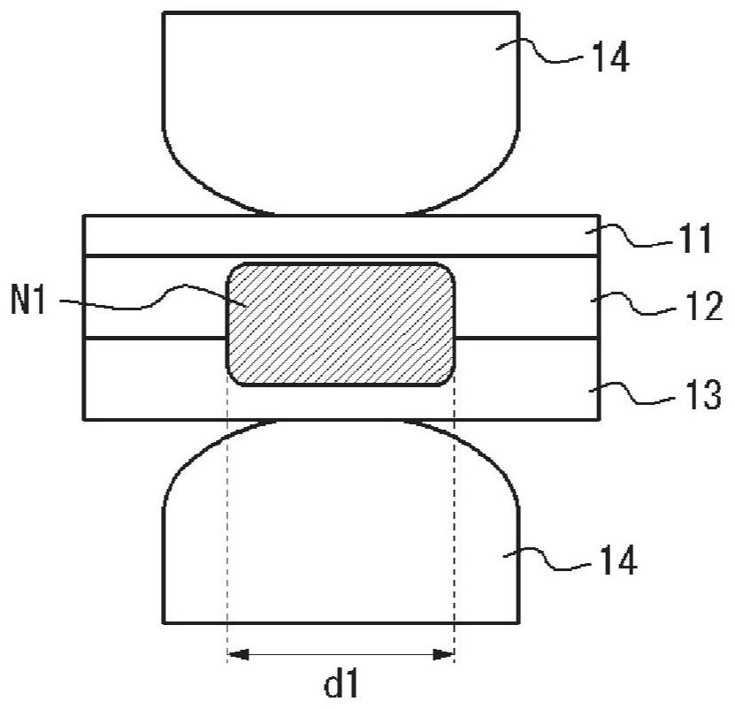
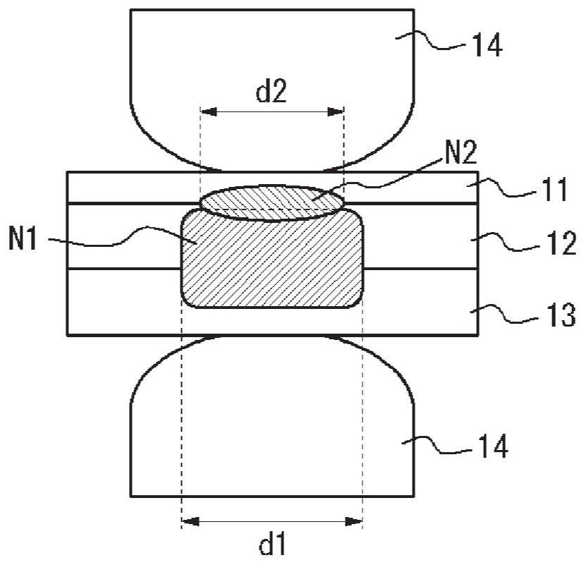
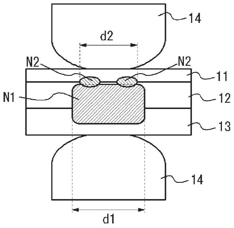
[0110] About Table 1 and Figure 1~4 The group of three overlapping steel plates shown was resistance spot welded under the conditions shown in Table 2 to produce joints.

[0111] Here, the case where the control mode in Table 2 is "constant current" shows the results when welding was performed by constant current control under the welding conditions shown in the table. On the other hand, when the control mode is "adaptive control", test welding is performed under the welding conditions shown in the table without interference such as a plate gap, and the time change of the instantaneous heating value per unit volume is stored. Thereafter, the results of adaptive control welding following the current value were performed based on the time-varying curve of the instantaneous calorific value per unit volume obtained by the test welding.

[0112] In addition, when making a part of the joint, such as Figure 4 As shown, spacers 15 (distance between spacers: 60 mm) were inserted be...


PUM


Abstract

The object of the present invention is to propose a plate group in which one of two or more superimposed thick plates is overlapped with a thin plate and the plate thickness ratio is large, so that no splashing can occur regardless of the degree of interference such as plate gaps and shunts. The resistance spot welding method that produces a nugget of appropriate diameter. In the present invention, there is provided a main welding process of superimposing a thin plate (11) on at least one of two or more thick plates (12, 13) that are superimposed using a pair of electrodes (14). A group of plates with a thickness ratio exceeding 3 is clamped and joined by applying current while applying pressure. In the actual welding process, the current application / pressurization pattern is divided into two or more multi-stage steps for welding. In this case, the first step The applied pressure F1 and the applied pressure F2 of the second step satisfy the relationship of F1>F2.

Description

technical field [0001] The present invention relates to resistance spot welding methods. In particular, the present invention is not affected by disturbances such as shunts, plate gaps, etc. in groups of two or more thick plates and three or more overlapping plates formed by overlapping thin plates on at least one of them. The nugget diameter can be stably ensured by spattering. Background technique [0002] Generally, the resistance spot welding method which is a kind of overlap resistance welding method is used for joining the superimposed steel plate. [0003] This welding method is a method in which two or more superimposed steel plates are clamped and pressed from above and below by a pair of electrodes, and a high-current welding current is applied to the upper and lower electrodes for a short time to join them. A dot-shaped welded portion can be obtained by resistance heating generated by flowing a high-current welding current. This point-shaped welded portion is c...

Claims


Application Information

Patent Timeline
Patent Type & Authority Patents(China)
IPC IPC(8): B23K11/20B23K11/11B23K11/24
CPCB23K11/24B23K11/115B23K11/20B23K11/255B23K11/257B23K11/11B23K11/16B23K11/362
Inventor 泽西央海冲田泰明松田广志池田伦正
Owner JFE STEEL CORP
Learn More