


Quick Research
Generate reliable direction feasibility study reports for your R&D in just a few steps.

Technical Q&A
Discover and master advanced knowledge NOW. Basics, ideas, possibilities, all at once.

Find Solutions
As an expert in R&D theories, this can generate solutions to your technical problems instantly.

Evaluate Feasibility
Analyze your overall solution with one click, know your potential R&D risks in advance.

Monitor Landscape
Get weekly tech updates, stay abreast of the latest tech innovations and key insights.
Self-grouting backpressure valve
A self-grouting and mud technology, which is applied in wellbore/well components, earthwork drilling, sealing/isolation, etc., can solve the problems of blocking water holes, reducing the strength of valve body, and high grouting cost, so as to prevent blowout and well kick , The effect of ensuring the safety of use
- Summary
- Abstract
- Description
- Claims
- Application Information
AI Technical Summary
Problems solved by technology
Method used
Image


Examples
Embodiment 1
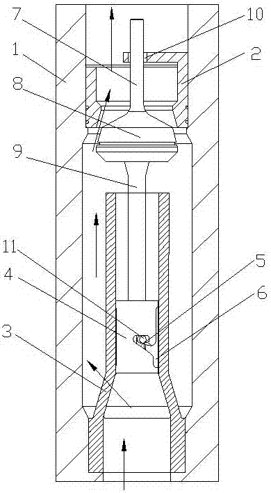
[0042] see figure 1 , a self-grouting back pressure valve, including a valve body 1, a valve core set in the valve body 1, a valve seat 2 and a support seat 3, the support seat 3 is located below the valve seat 2, and the support seat 3 is set There is a sliding sleeve 4, and the sliding sleeve 4 is provided with a lateral hanging groove 5 and a vertical sliding groove 6, the lateral hanging groove 5 and the vertical sliding groove 6 communicate, and the valve core includes an upper valve stem connected together 7. Tapered block 8 and lower valve stem 9, the valve seat 2 is provided with a guide hole 10 for the axial movement of the upper valve stem 7, the upper valve stem 7 runs through the guide hole 10, and the lower valve stem 9 is provided with a hanger Pin 11, the hanger pin 11 is hooked on the sliding sleeve 4.
[0043] This embodiment is the most basic implementation, including a valve body, a valve core arranged in the valve body, a valve seat and a support seat, the...
Embodiment 2
[0045] see figure 2 , a self-grouting back pressure valve, including a valve body 1, a valve core set in the valve body 1, a valve seat 2 and a support seat 3, the support seat 3 is located below the valve seat 2, and the support seat 3 is set There is a sliding sleeve 4, and the sliding sleeve 4 is provided with a lateral hanging groove 5 and a vertical sliding groove 6, the lateral hanging groove 5 and the vertical sliding groove 6 communicate, and the valve core includes an upper valve stem connected together 7. Tapered block 8 and lower valve stem 9, the valve seat 2 is provided with a guide hole 10 for the axial movement of the upper valve stem 7, the upper valve stem 7 runs through the guide hole 10, and the lower valve stem 9 is provided with a hanger Pin 11, the hanger pin 11 is hooked on the sliding sleeve 4.
[0046] A return spring 12 is sleeved on the lower valve stem 9 , one end of the return spring 12 is in contact with the tapered block 8 , and the other end i...
Embodiment 3
[0049] see image 3 , a self-grouting back pressure valve, including a valve body 1, a valve core set in the valve body 1, a valve seat 2 and a support seat 3, the support seat 3 is located below the valve seat 2, and the support seat 3 is set There is a sliding sleeve 4, and the sliding sleeve 4 is provided with a lateral hanging groove 5 and a vertical sliding groove 6, the lateral hanging groove 5 and the vertical sliding groove 6 communicate, and the valve core includes an upper valve stem connected together 7. Tapered block 8 and lower valve stem 9, the valve seat 2 is provided with a guide hole 10 for the axial movement of the upper valve stem 7, the upper valve stem 7 runs through the guide hole 10, and the lower valve stem 9 is provided with a hanger Pin 11, the hanger pin 11 is hooked on the sliding sleeve 4.
[0050] The supporting base 3 is provided with an annular baffle 13, the center of the annular baffle 13 has a through hole, the lower valve stem 9 runs throug...
PUM
 Abstract
Description
Claims
Application Information
 - R&D Engineer
- R&D Manager
- IP Professional
- Industry Leading Data Capabilities
- Powerful AI technology
- Patent DNA Extraction
Browse by: Latest US Patents, China's latest patents, Technical Efficacy Thesaurus, Application Domain, Technology Topic, Popular Technical Reports.
© 2024 PatSnap. All rights reserved.Legal|Privacy policy|Modern Slavery Act Transparency Statement|Sitemap|About US| Contact US: help@patsnap.com