A high-efficiency steam box mechanism

A steamer and high-efficiency technology, applied to multi-unit cooking utensils, kitchen utensils, household utensils, etc., can solve the problems of delaying the speed of cooking, food overturning, and inability to meet various needs

Active Publication Date: 2019-01-04
TANGZHOU QIANGMING ELECTROTHERMAL APPLIANCE CO LTD
View PDF6 Cites 0 Cited by
  • Summary
  • Abstract
  • Description
  • Claims
  • Application Information

AI Technical Summary

Problems solved by technology

[0002] At present, steamers are more and more widely used in the kitchens of major hotels. With the widespread use of steamers, accidents often occur that the hands of operators are burned by steam. In the past, steamers generally needed to be pushed and pulled by hand. rack to take out the steamed food from the steamer. During this process, the above-mentioned accidents will inevitably occur, and manual pushing and pulling of the rack will easily cause unstable force, which will easily cause the food on the rack to overturn. There is a greater danger; in the prior art, there is also a steam box with an automatic delivery device, but it can only manipulate the entry and exit of one shelf at a time, and cannot achieve selectivity or move out the shelf at the same time, which cannot meet the multiple needs of steaming food. This kind of demand also greatly delays the speed of serving dishes, which brings great inconvenience to users

Method used


Image

  • A high-efficiency steam box mechanism
  • A high-efficiency steam box mechanism
  • A high-efficiency steam box mechanism

Examples


Embodiment Construction

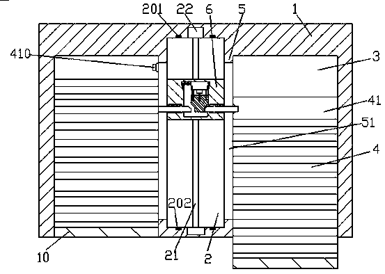
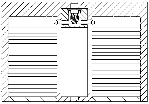
[0017] Such as Figure 1-Figure 5 As shown, a kind of high-efficiency steam box mechanism of the present invention comprises box body 1, and described box body 1 is provided with cavity 3 and the sliding cavity 2 between described cavity 3 symmetrically, and described A baffle plate 5 with a rail groove 51 is provided between the sliding chamber 2 and the cavity 3, a storage plate 4 is provided in the cavity 3, a straight plate 41 is provided on the rear plane of the storage plate 4, and the sliding A No. 1 screw rod 21 is provided in the transfer chamber 2, and a manipulation part 6 is threadedly fitted on the No. 1 screw rod 21. A manipulation chamber 61 is provided in the manipulation part 6, and opposite sides are provided on both sides of the top of the manipulation chamber 61. Set up a settling groove 7, the settling groove 7 is provided with a No. 1 guide rod 71, and the No. 1 guide rod 71 is provided with a straight part 9 that slides and fits left and right, and the t...


PUM


Abstract

The invention discloses an efficient steaming box mechanism, comprising a box body; cavities in bilateral symmetry and a sliding cavity between the cavities are arranged in the box body, a retaining plate with a rail groove is arranged between the sliding cavity and each cavity, a holding plate is arranged in each cavity, the rear plane of each holding plate is a straight plate, a first screw is arranged in each sliding cavity, an operating portion is threadedly fitted to each first screw, an operating cavity is arranged in each operating part, and two sides of the top end of each operating cavity are provided with opposite mounting grooves, a first guide rod is arranged in each mounting groove, and each first guide rod is provided with a straight portion that is in side-to-side sliding fit.

Description

technical field [0001] The invention relates to the field of kitchen equipment, in particular to an efficient steam box mechanism. Background technique [0002] At present, steamers are more and more widely used in the kitchens of major hotels. With the widespread use of steamers, accidents often occur that the hands of operators are burned by steam. In the past, steamers generally needed to be pushed and pulled by hand. rack to take out the steamed food from the steamer. During this process, the above-mentioned accidents will inevitably occur, and manual pushing and pulling of the rack will easily cause unstable force, which will easily cause the food on the rack to overturn. There is a greater danger; in the prior art, there is also a steam box with an automatic sending device, but it can only manipulate the entry and exit of one shelf at a time, and cannot achieve selectivity or move out the shelf at the same time, which cannot meet the multiple needs of steaming food. T...

Claims


Application Information

Patent Timeline
Patent Type & Authority Patents(China)
IPC IPC(8): A47J27/16A47J27/12
CPCA47J27/12A47J27/16
Inventor 黄陈凯
Owner TANGZHOU QIANGMING ELECTROTHERMAL APPLIANCE CO LTD
Why Eureka
Try Eureka