
Well cementation cement sheath integrity analysis and forecast method and device

A technology of cementing cement and prediction method, which is applied in special data processing applications, instruments, electrical digital data processing, etc., and can solve problems such as seal failure and actual working conditions at the bottom of the well that cannot be truly reflected

Active Publication Date: 2017-07-28
BC P INC CHINA NAT PETROLEUM CORP +2
View PDF4 Cites 17 Cited by
  • Summary
  • Abstract
  • Description
  • Claims
  • Application Information

AI Technical Summary

Problems solved by technology

In addition, some researchers combined plastic mechanics to analyze the detachment of the interface between the cement sheath and the casing due to plastic deformation under plastic deformation conditions, resulting in micro-annulus gaps and sealing failure.
[0004] However, these two types of analysis methods are too simplified, and many actual working conditions at the bottom of the well cannot be truly reflected.

Method used


Image

  • Well cementation cement sheath integrity analysis and forecast method and device
  • Well cementation cement sheath integrity analysis and forecast method and device
  • Well cementation cement sheath integrity analysis and forecast method and device

Examples


Embodiment 1

[0372] Embodiment 1: A cementing-interface bonding strength testing device, including the cementing main body, the upper clamping part and the lower clamping part described in the cementing-interface bonding strength maintenance device;

[0373] The cementing-interface bonding strength maintenance device includes at least one cementing body, and the cementing body includes:

[0374]The curing cylinder is formed by clamping a plurality of cylinder blocks along the axial direction of the curing cylinder, and has an upper end opening and a lower end opening;

[0375] The lower sealing body supports and seals the lower opening;

[0376] The upper sealing device includes an upper sealing body and a force transmission screw, the force transmission screw is vertically connected to the lower surface of the upper sealing body, the upper sealing body fixes and seals the upper opening, and the force transmission screw extends into the inner cavity of the curing cylinder;

[0377] Where...

Embodiment 2

[0380] Embodiment 2: In the cementing-interface bonding strength testing device as described in Embodiment 1, two adjacent cylinder blocks are clamped together through their stepped side ends.

Embodiment 3

[0381] Embodiment 3: The cementing-interface bonding strength testing device as described in Embodiment 1, the curing cylinder is in the shape of a cylinder.


PUM


Abstract

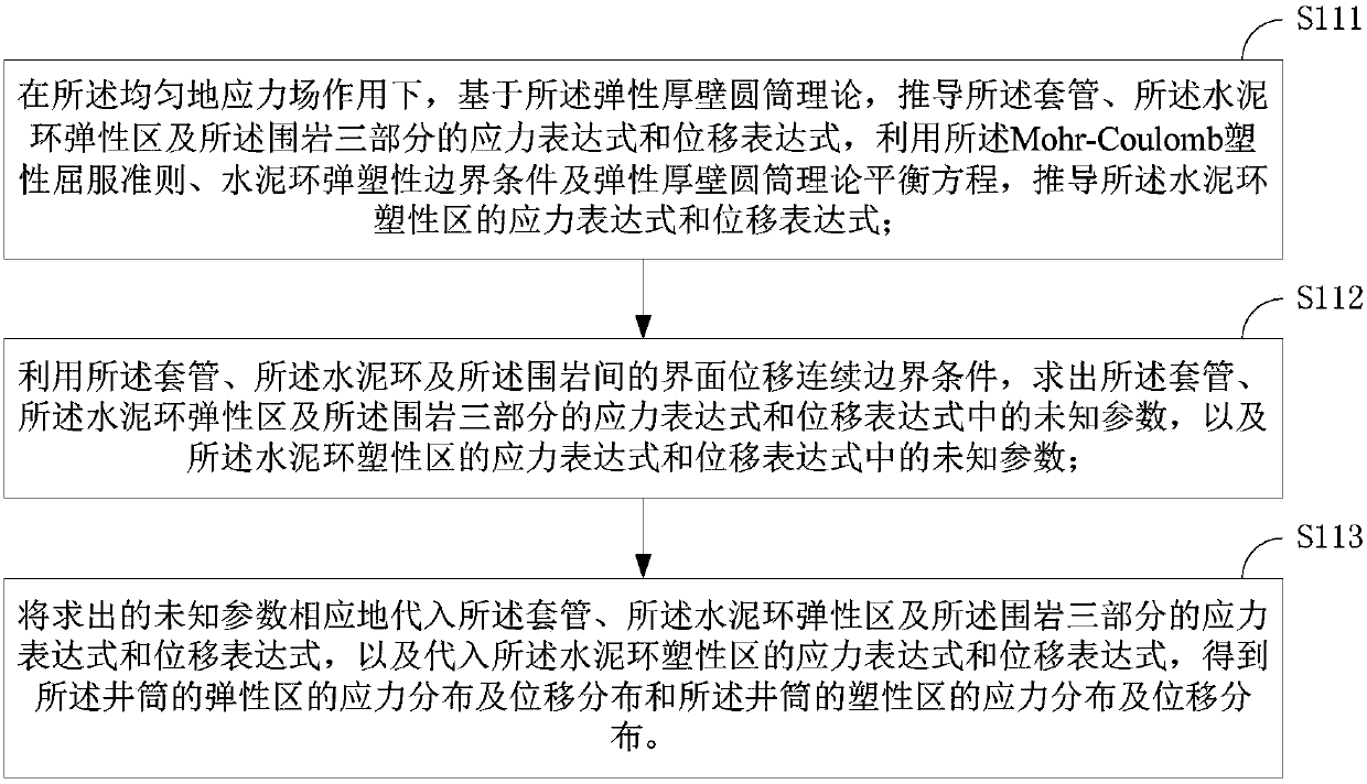
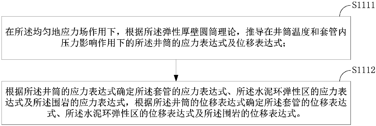
The invention provides a well cementation cement sheath integrity analysis and forecast method and device. The method comprises the steps that under a homogeneous crustal stress field, and based on the elastic thick wall cylinder theory and Mohr-Coulomb plastic yield guidelines respectively, the stress distribution and the displacement distribution of an elastic area of the well pitshaft and the stress distribution and the displacement distribution of the plasticity of the pitshaft area are calculated and obtained, the pitshaft area comprises a casing pipe, a cement ring and the surrounding rocks distributed from the inside to the outside; the stress distribution and the displacement distribution of the well pitshaft under the inhomogeneous stress field using the Airy stress function are calculated and obtained, the homogeneous stress field and inhomogeneous stress field are linearly overlaid and the result is the original stress field; the stress distribution and the displacement distribution of the pitshaft plastic area, and the stress distribution and displacement distribution of the pitshaft under the inhomogeneous stress field are utilized and linearly super-imposed to obtain the total stress distribution and displacement distribution in the pitshaft, which is used for the analysis and forecasting of cement sheath integrity. The well cementation cement sheath integrity analysis and forecast method and device take into account the cement sheath elastic plasticity, to reflect the work conditions of the real well bottom.

Description

technical field [0001] The invention relates to the technical field of casing cementing oil and gas wells, in particular to a method and device for analyzing and predicting the integrity of a cement sheath. Background technique [0002] The cement sheath is an important barrier to ensure the effective sealing of the wellbore. How to ensure the integrity of the cement sheath is a concern of cementing engineers. In order to improve the sealing performance of the wellbore and ensure the integrity of the cement sheath, researchers have developed several sets of cement slurry systems, such as high density, low density, low elastic modulus, high strength, toughness and micro expansion, etc. However, due to the complexity of the working conditions at the bottom of the well, there are still a large number of cement sheath seal failure problems. [0003] In order to ascertain the cause of cement sheath seal failure, many researchers use the principle of elastic mechanics to start w...

Claims


Application Information

Patent Timeline
IPC IPC(8): G06F17/50
CPCG06F30/13G06F30/20
Inventor 李勇沈吉云纪宏飞袁进平靳建洲刘斌辉江乐张华张弛郭玉超
Owner BC P INC CHINA NAT PETROLEUM CORP
Learn More