
Driving gear structure of double-layer toner cartridge

A technology for driving gears and toner cartridges, which is applied in the field of toner cartridges, can solve the problems of single function, large area of ​​the end face of the drive end of the powder bin, and inability to install, so as to promote the progress of the industry, improve printing quality, and reduce the end face area.

Pending Publication Date: 2017-07-28
珠海天麟医疗器械科技有限公司
View PDF7 Cites 1 Cited by
  • Summary
  • Abstract
  • Description
  • Claims
  • Application Information

AI Technical Summary

Problems solved by technology

[0002] At present, the original manufacturers on the market will design and produce specially matched magnetic toner cartridge printers for their magnetic toner cartridge printers, and in order to achieve the purpose of only using magnetic toner cartridges and not non-magnetic toner cartridges, they will design the size of the magnetic toner cartridges to be relatively small At the same time, the size of the printer’s landing position is also designed to match the size of the magnetic toner cartridge (due to the large size of the shell at the powder feeding port of the non-magnetic toner cartridge, it cannot be installed on the original magnetic toner cartridge printer), so it is very The market competitiveness of magnetic toner cartridges is extremely limited, and because the price of magnetic toner is much higher than that of non-magnetic toner, users need to pay more for long-term use
[0003] In addition, the driving teeth of the developing roller and the driving teeth of the powder feeding roller of the non-magnetic toner cartridges currently on the market are directly meshed with the main driving teeth and started synchronously. With powder feeding function, single function

Method used


Image

  • Driving gear structure of double-layer toner cartridge
  • Driving gear structure of double-layer toner cartridge
  • Driving gear structure of double-layer toner cartridge

Examples


Embodiment Construction

[0017] In order to make the object, technical solution and advantages of the present invention clearer, the present invention will be further described in detail below in conjunction with the accompanying drawings and embodiments. It should be understood that the specific embodiments described here are only used to explain the present invention, not to limit the present invention.

[0018] Such as Figure 1 to Figure 3 as shown in:

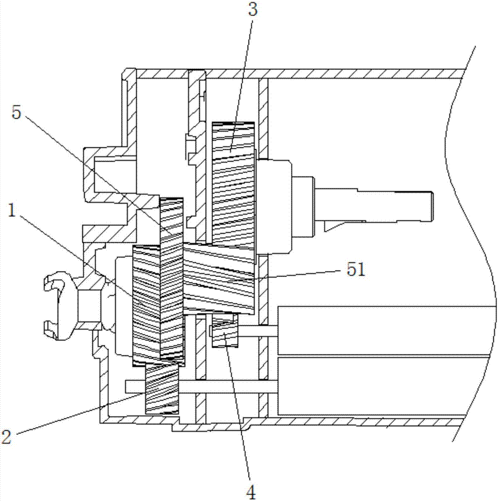
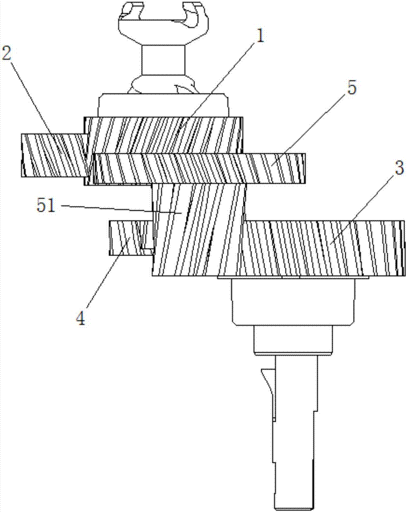
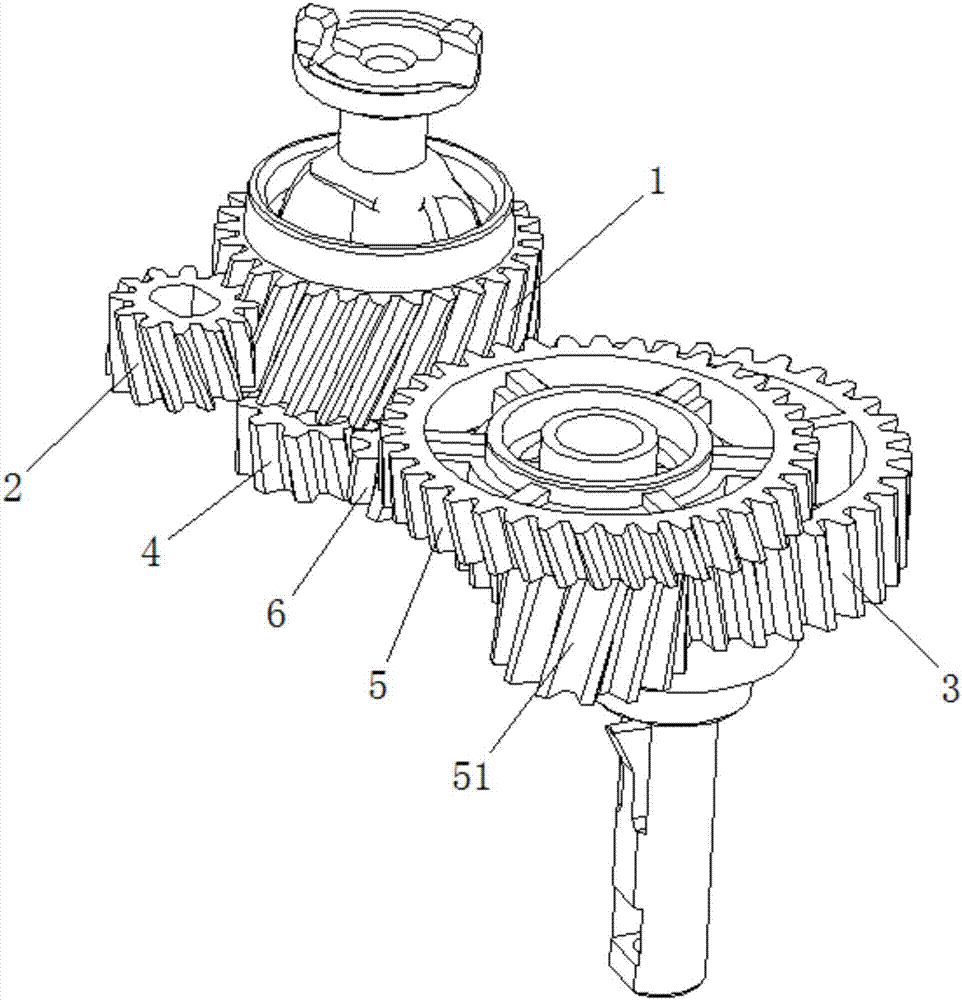
[0019] The embodiment of the present invention provides a driving tooth structure of a double-layer toner cartridge, which includes a main driving tooth 1 and a developing roller driving tooth 2 arranged on the outer layer and connected to each other, and a stirring tooth 3 and a powder feeding roller arranged on the inner layer. The roller driving tooth 4, and the main driving tooth 1, the stirring tooth 3 and the powder feeding roller driving tooth 4 are sequentially connected by transmission. The specific structure can be: the driving tooth s...


PUM


Abstract

The invention relates to a driving gear structure of a double-layer toner cartridge. The driving gear structure comprises a main driving gear and a develop roller driving gear which are arranged on an outer layer, and are meshed with each other, and a stirring gear and a powder feeding roller driving gear which are arranged on the inner layer; the main driving gear, the stirring gear, and the powder feeding roller driving gear are connected successively via drive connection. The driving gear structure is invented based on a novel driving method and driving principles; at least parts of the driving gears of the outer layer and the inner layer are overlapped in the longitudianl direction; occupied area is small; structure is compact and skilful; modification of magnetic toner cartridges into non-magnetic toner cartridges is realized; the non-magnetic toner cartridges can be used in original magnetic toner cartridge printers; user application cost is reduced; the monopoly of original manufacturers is broken; it is beneficial for development of manufacturers of non-magnetic toner cartridges and regenerated toner cartridges; industry development is promoted; nonsynchronous initiation of the powder feeding roller and the develop roller is realized; the surface of the develop roller is washed before running of the toner cartridge; and toner cartridge printing quality is increased.

Description

technical field [0001] The invention belongs to the technical field of toner cartridges, in particular to a driving tooth structure of a double-layer toner cartridge. Background technique [0002] At present, the original manufacturers on the market will design and produce specially matched magnetic toner cartridge printers for their magnetic toner cartridge printers, and in order to achieve the purpose of only using magnetic toner cartridges and not non-magnetic toner cartridges, they will design the size of the magnetic toner cartridges to be relatively small At the same time, the size of the printer’s landing position is also designed to match the size of the magnetic toner cartridge (due to the large size of the shell at the powder feeding port of the non-magnetic toner cartridge, it cannot be installed on the original magnetic toner cartridge printer), so it is very The market competitiveness of magnetic toner cartridges is extremely limited, and because the price of ma...

Claims


Application Information

Patent Timeline
IPC IPC(8): G03G21/18
CPCG03G21/186
Inventor 赵祝论陈佳茂
Owner 珠海天麟医疗器械科技有限公司
Learn More