
Planing cutter with leftward spiral cutting edge and rightward spiral cutting edge being located on same circumference

A technology of left and right spirals and blades, which is applied in special forming/shaping machines, processing machines for manufacturing flat surfaces, forming/shaping machines, etc., can solve the problems of uneven deep and shallow stripes, surface depressions, etc., and achieve force balance , stable feeding, and the effect of improving the utilization rate of the plate

Pending Publication Date: 2017-07-28
YANTAI LIMIN MAHOGANY FURNITURE
View PDF6 Cites 2 Cited by
  • Summary
  • Abstract
  • Description
  • Claims
  • Application Information

AI Technical Summary

Problems solved by technology

[0003] The invention provides a planer with left and right helical blades on the same circumference, which solves the disadvantages in the background art that longitudinal uneven deep and shallow stripes and surface depressions are easily formed when the blade is cut in a single helical direction.

Method used


Image

  • Planing cutter with leftward spiral cutting edge and rightward spiral cutting edge being located on same circumference

Examples


Embodiment Construction

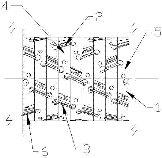
[0010] For a better understanding and implementation, the present invention will be further described below in conjunction with the accompanying drawings: the planer that is provided with left and right spiral blades on the same circumference includes a planer 5, and the cutter body 1 of the planer 5 is provided with a plurality of sipes. A blade 6 is installed inside, and a plurality of left-handed blades 3 and right-handed blades 2 are arranged on any section of the circumference of the cutter body 1, and the left-handed blades 3 and the right-handed blades 2 are arranged at intervals, forming a shape on any section of the circumference of the cutter body 1. The left-handed and right-handed blades are arranged at intervals between the double-handed blade group 4. When the double-handed blade group 4 cuts the plate, the alternate cutting of the left and right-handed blades better reduces the risk of damage caused by the planer during the planing process. Horizontal and longitu...


PUM


Abstract

The invention provides a planing cutter with a leftward spiral cutting edge and a rightward spiral cutting edge being located on the same circumference. The planing cutter with the leftward spiral cutting edge and the rightward spiral cutting edge being located on the same circumference comprises a planing cutter body. A cutter main body of the planing cutter body is provided with multiple cutter slots. Blades are installed in the cutter slots. A double-spiral-direction cutting edge group is arranged on any circumference of the main cutter body. Each double-spiral-direction cutting edge group at least comprises one leftward spiral cutting edge and one rightward spiral cutting edge. The leftward spiral cutting edge and the rightward spiral cutting edge are arranged in a spaced manner. According to the planing cutter with the leftward spiral cutting edge and the rightward spiral cutting edge being located on the same circumference, the manner that the leftward spiral cutting edge for cutting and the rightward spiral cutting edge for cutting are arranged on any circumference of the planing cutter at the same time and alternately and cooperatively plane a board is adopted, so that the surface indentations of the planed board are reduced, the flatness and smoothness degree and the board utilization rate are improved, the planed board is stably fed, the up-and-down resonance effect is relieved, and transverse and longitudinal irregular wavy lines are not generated.

Description

technical field [0001] The invention belongs to the technical field of woodworking equipment, and in particular relates to a planer with left and right spiral blades on the same circumference. Background technique [0002] Currently on the market, planers used on woodworking planers or end milling machines, although the blades are installed in the grooves provided by the spiral, the blades on the blades still do not have a spiral effect, that is, the blades still cut plates in parallel. The applicant's application The patent No. "2015105251693, the invention name is adjustable combined spiral planer", discloses a left inclined cutter body and a right inclined cutter body. There are blades installed in the cutter body, and the arc-shaped blades on the blades are arranged on the planer. The left helical blades on one circumference and the right helical blades on one circumference are spaced apart from each other, that is, arranged at intervals from left to right along the long...

Claims


Application Information

Patent Timeline
IPC IPC(8): B27C1/00B27C5/00
CPCB27C1/00B27C5/00
Inventor 邢秋平邢海东
Owner YANTAI LIMIN MAHOGANY FURNITURE
Learn More