
Power demand response control system and load control method therefor

A power demand response and control system technology, applied in power network operating system integration, information technology support systems, circuit devices, etc., can solve problems such as inability to fully tap user-controllable resources and complexity, and achieve high practical value and computational complexity. Small, easy-to-achieve effects

Active Publication Date: 2017-07-21
山东正晨科技股份有限公司
View PDF3 Cites 1 Cited by
  • Summary
  • Abstract
  • Description
  • Claims
  • Application Information

AI Technical Summary

Problems solved by technology

[0003] The current research on how residential users participate in demand response either only considers the demand response scheduling problem of part of the load in residential users, and cannot fully tap the controllable resources on the user demand side; or establishes an accurate and complex electrical energy consumption description model With the scheduling strategy, it takes a lot of calculations to get the scheduling result

Method used


Image

  • Power demand response control system and load control method therefor
  • Power demand response control system and load control method therefor
  • Power demand response control system and load control method therefor

Examples


Embodiment Construction

[0027] The present invention will be further described below with reference to the drawings and embodiments.

[0028] It should be pointed out that the following detailed descriptions are all illustrative and are intended to provide further explanations for the application. Unless otherwise indicated, all technical and scientific terms used herein have the same meaning as commonly understood by those of ordinary skill in the technical field to which this application belongs.

[0029] It should be noted that the terms used here are only for describing specific embodiments, and are not intended to limit the exemplary embodiments according to the present application. As used herein, unless the context clearly indicates otherwise, the singular form is also intended to include the plural form. In addition, it should also be understood that when the terms "comprising" and / or "including" are used in this specification, they indicate There are features, steps, operations, devices, compone...


PUM


Abstract

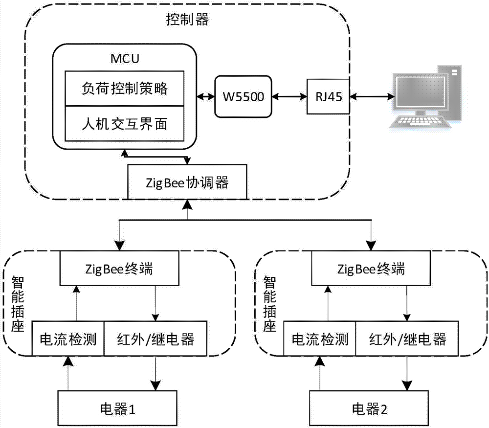
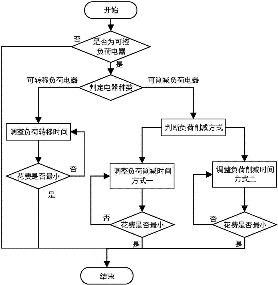
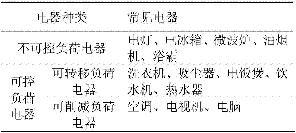
The invention discloses a power demand response control system and method, and the system comprises a controller and intelligent sockets disposed at positions of all users. Each intelligent socket is configured to achieve the start / stop control of an electric appliance, the current data collection and the transmission of current data to the controller. The controller is used for building a relation model of a corresponding period power consumption quantity and the working time according to the load type of each electric appliance in the house of a user, determining the operation time of the electric appliance through combining the electricity charge of each time period and taking the minimum electricity expenditure as the precondition, formulating an electric appliance control strategy, transmitting the electric appliance control strategy to the intelligent sockets, and enabling the user to automatically participate in the demand response based on time-of-use electricity price. The method is small in calculation burden, is easy to implement in a common embedded controller, and is higher in practical value.

Description

Technical field [0001] The invention relates to a power demand response control system and a load control method thereof. Background technique [0002] As the electricity consumption of residential users increases year by year, the peak-to-valley difference of power load gradually increases, which is not conducive to the economic operation of the power grid. To solve this problem, electricity demand response projects based on time-of-use electricity prices have been widely implemented. However, due to the lack of a demand response controller that can operate automatically, and the timeliness and urgency of residential load electricity consumption, residents are unwilling to adjust the running time of electrical appliances and reduce electricity costs even if electricity costs are high most of the time . Therefore, it is necessary to design demand response controllers for residential users and promote their participation in power demand response. [0003] The current research on ...

Claims


Application Information

Patent Timeline
Patent Type & Authority Applications(China)
IPC IPC(8): H02J3/14
CPCH02J3/14H02J2310/64Y02B70/30Y02B70/3225Y04S20/222Y04S20/242
Inventor 李歧强王彦邦王鲁浩
Owner 山东正晨科技股份有限公司
Learn More