
Double-shaft multi-optical path channel switching device suitable for large solar telescope

A channel switching device, solar telescope technology, applied in the direction of installation, optics, optical components, etc., can solve the problems of high precision requirements for support mechanisms and switching structures, limited space size, and not allowed to block the optical path, etc., to meet high-precision positioning requirements , the effect of compact structure

Active Publication Date: 2017-07-21
NANJING INST OF ASTRONOMICAL OPTICS & TECH NAT ASTRONOMICAL OBSE
View PDF3 Cites 2 Cited by
  • Summary
  • Abstract
  • Description
  • Claims
  • Application Information

AI Technical Summary

Problems solved by technology

[0004] The Gregorian focus F2 is located in the center of the lens barrel, and its front end needs to be arranged with two components, the magnetic analysis instrument and the second field of view diaphragm. At present, there are technical problems to be solved: 1) The two components need a support mechanism, the support mechanism Need to have full degree of freedom adjustment and locking function; 2) Magnetic analysis instrument needs to switch structure to realize cutting in and out; 3) The second field of view diaphragm also needs to switch mechanism to realize switching between different sizes of diaphragm; 4) Support mechanism and switching The structure requires high precision and is limited by the size of the space; 5) the support and switching mechanism itself and the parts are not allowed to block the optical path in the cut-out position

Method used


Image

  • Double-shaft multi-optical path channel switching device suitable for large solar telescope
  • Double-shaft multi-optical path channel switching device suitable for large solar telescope
  • Double-shaft multi-optical path channel switching device suitable for large solar telescope

Examples


Embodiment Construction

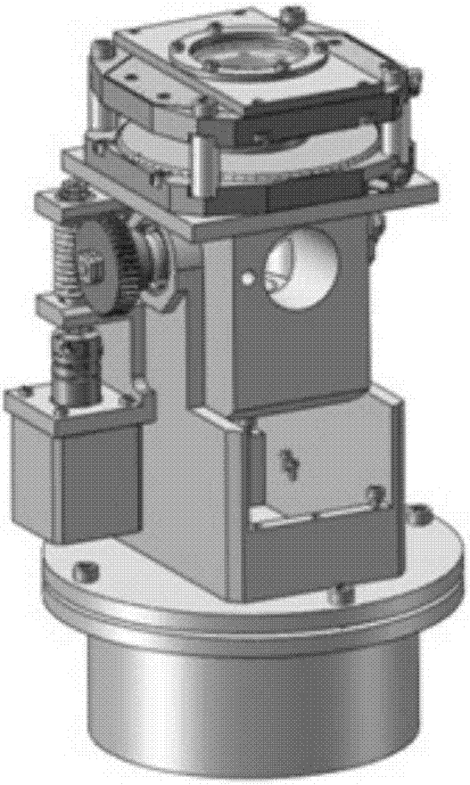
[0021] The overall structure schematic diagram of the present invention is as figure 1 shown.

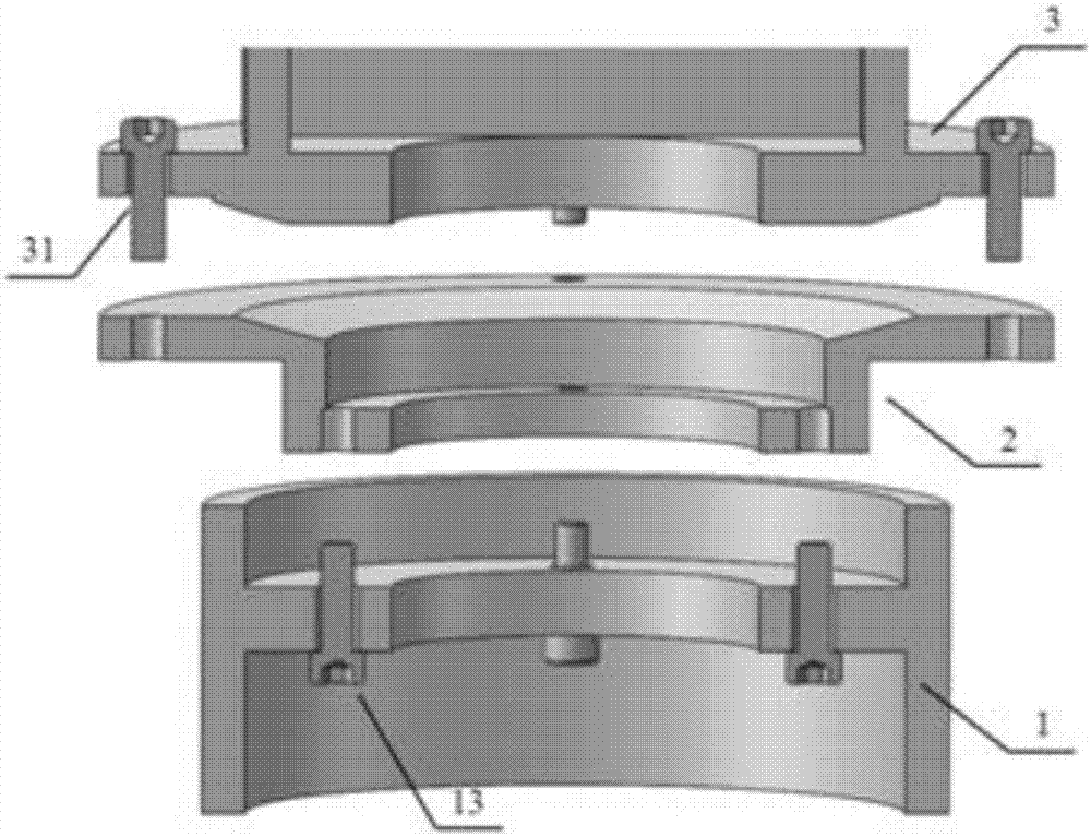
[0022] The radial adjustment seat 1 is a cylindrical hollow inside, and an annular partition 12 is arranged inside it, such as image 3 and Figure 4 Shown; Its top of inclination adjustment seat 2 is a disk shape, and its bottom is cylindrical, and the center has a circular hole; When placed in the radial adjustment seat 1, there is a gap between the cylindrical outer wall of the inclination adjustment seat 2 and the inner wall of the radial adjustment seat 1, so that the inclination adjustment seat 2 has two radial translation adjustments in the gap of the radial adjustment seat 1 degrees of freedom. The radial adjustment seat 1 and the inclination adjustment seat 2 are threadedly connected by adjusting screws 13 .

[0023] There is a concave arc-shaped design at the joint between the disk and the cylinder of the tilt adjustment seat 2 . The bottom of support 3 is also a disc...


PUM


Abstract

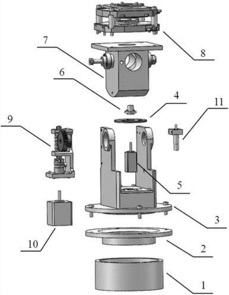
Provided is a double-shaft multi-optical path channel switching device suitable for a large solar telescope. The switching device consists of a radial adjusting seat 1, an inclined fixed seat 2, a support 3, a view field diaphragm 4, a vertical rotation shaft motor 5, an axial adjusting seat 6, a double-channel rotation shaft 7, a polarization device 8, a driving worm and gear pair 9, a horizontal rotation motor 10, a positioning switch 11, a connection plate 43, a circular separation plate 12, a locking screw 42, an adjusting screw 13, an adjusting screw 31 and an adjusting screw 41. According to the invention, rapid switching and precise positioning of polarization devices or other optical devices can be achieved through computer control; rapid switching and precise positioning of different sizes of view field diaphragms or other devices can be achieved through computer control; by setting a five-dimensional manual adjusting mechanism, positions of the polarization devices and the diaphragms can be precisely adjusted and firmly locked; and the switching device is compact in structure and will not shield optical paths.

Description

technical field [0001] The invention relates to the field of structural design of astronomical telescopes, in particular to the support and switching structure design of a polarization device and a field of view diaphragm at the focal point of a large solar telescope F2. Background technique [0002] Large-scale solar telescopes are generally equipped with multiple focal points for arranging different functional components, such as the thermal field of view diaphragm at the main focus F1; the Gregorian focal point F2 with magnetic analysis instruments and the second field of view diaphragm; the folding axis focus F3 is equipped with various scientific instruments. [0003] For the magnetic analysis instrument arranged in front of F2, it is necessary to have the function of moving in and out of the optical path, so as to avoid frequent removal and replacement of the magnetic analysis instrument when the telescope switches between magnetic field measurement and other observati...

Claims


Application Information

Patent Timeline
IPC IPC(8): G02B7/00
CPCG02B7/00
Inventor 顾伯忠姜翔叶宇朱冉
Owner NANJING INST OF ASTRONOMICAL OPTICS & TECH NAT ASTRONOMICAL OBSE
Learn More