
Signal injection system for hardware-in-loop testing

A technology for injecting systems and signals, applied in the direction of test/monitoring control systems, general control systems, control/regulation systems, etc. It can solve the problems of failure to achieve injection tests, unclear signal fault logic, and difficult to change CAN message fault injection, etc. question

Active Publication Date: 2021-09-28
ANHUI JIANGHUAI AUTOMOBILE GRP CORP LTD
View PDF9 Cites 0 Cited by
  • Summary
  • Abstract
  • Description
  • Claims
  • Application Information

AI Technical Summary

Problems solved by technology

[0003] When the real controller node is online, if it is necessary to implement fault injection such as effective bits, error values, logic errors, etc. of the signal, the conventional method is to indirectly implement controller error signal injection by injecting related device faults. Due to the fact that some signal failure logics are not clear or the components involved are not open to customize relevant fault information, etc., this existing method cannot fully cover the injection test of all valid bits, error values ​​and other signals sent by the controller. , that is, the existing multi-node integrated hardware-in-the-loop test method, it is difficult to change the CAN message sent by the real controller node to achieve fault injection

Method used


Image

  • Signal injection system for hardware-in-loop testing

Examples


Embodiment Construction

[0024] Embodiments of the present invention are described in detail below, and examples of the embodiments are shown in the drawings, wherein the same or similar reference numerals denote the same or similar elements or elements having the same or similar functions throughout. The embodiments described below by referring to the figures are exemplary only for explaining the present invention and should not be construed as limiting the present invention.

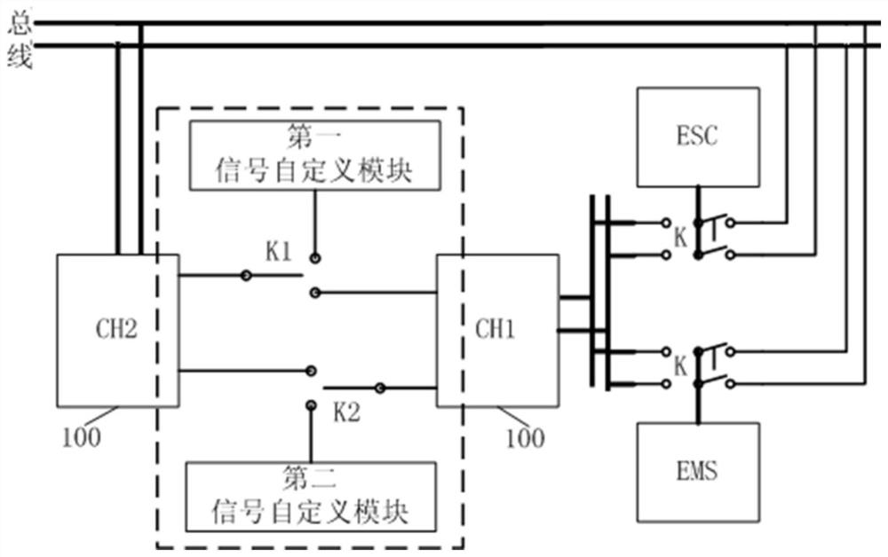
[0025] The present invention proposes an embodiment of a signal injection system for hardware-in-the-loop testing, specifically, as figure 1 As shown, it may include: a bus board 100 and a number of double-pole double-throw switches K corresponding to the number of real controller nodes.

[0026] Specifically, the first channel CH1 of the bus board 100 is connected to the first static end (or fixed end, static contact end, etc.) The second static end of the throw switch K is respectively connected to the bus of the hardware-i...


PUM


Abstract

The invention discloses a signal injection system for hardware-in-loop testing, which has the design concept that two sections of parallel communication networks are constructed through two channels of a bus board card, and a virtual gateway with a data path switching mechanism is established between the two sections of parallel communication networks to realize injection of a self-defined signal; moreover, the communication relationship between the real controller node and the first channel or bus is realized through a hardware switch, so that the multi-node signal injection operation is realized. According to the invention, full coverage of multi-node hardware-in-loop test signal injection is realized, and meanwhile, the tested node receives messages of other nodes in the network through the parallel network, so that the conditions of false alarm codes and the like are avoided.

Description

technical field [0001] The invention relates to the field of hardware-in-the-loop testing, in particular to a signal injection system for hardware-in-the-loop testing. Background technique [0002] Hardware-in-the-loop testing has become an important part of the vehicle controller development model. At present, many host manufacturers have shifted from hardware-in-the-loop testing of a single controller to integrated HIL testing of multiple controllers. Integrated HIL testing can be performed simultaneously on multiple nodes. In the case of , test and verify the interaction between subsystems. [0003] When the real controller node is online, if it is necessary to implement fault injection such as effective bits, error values, logic errors, etc. of the signal, the conventional method is to indirectly implement controller error signal injection by injecting related device faults. Due to the fact that some signal failure logics are not clear or the components involved are not...

Claims


Application Information

Patent Timeline
IPC IPC(8): G05B23/02
CPCG05B23/0213G05B23/0256Y02P90/02
Inventor 史雪纯乔瞾张文明温敏徐洪伟
Owner ANHUI JIANGHUAI AUTOMOBILE GRP CORP LTD
Learn More