
A paper machine wet end exhaust system

A paper machine and wet end technology, applied in the field of paper machine wet end exhaust system, can solve the problems of frequent fan failures, poor exhaust effect, and inability to effectively discharge moisture, so as to improve the on-site environment, eliminate water mist, improve Effects of Convenience and Operational Efficiency

Active Publication Date: 2019-01-29
NINE DRAGONS PAPER TAICANG LTD
View PDF9 Cites 0 Cited by
  • Summary
  • Abstract
  • Description
  • Claims
  • Application Information

AI Technical Summary

Problems solved by technology

However, due to the high humidity of the pumped gas and the fiber contained in the water mist, the exhaust effect is poor, the fan failure is frequent, and the maintenance cost is high. At the same time, the moisture cannot be effectively discharged, resulting in large water mist inside and outside the rack It is easy to accumulate sludge, which reduces the operating efficiency of the paper machine

Method used


Image

  • A paper machine wet end exhaust system
  • A paper machine wet end exhaust system
  • A paper machine wet end exhaust system

Examples


Embodiment 1

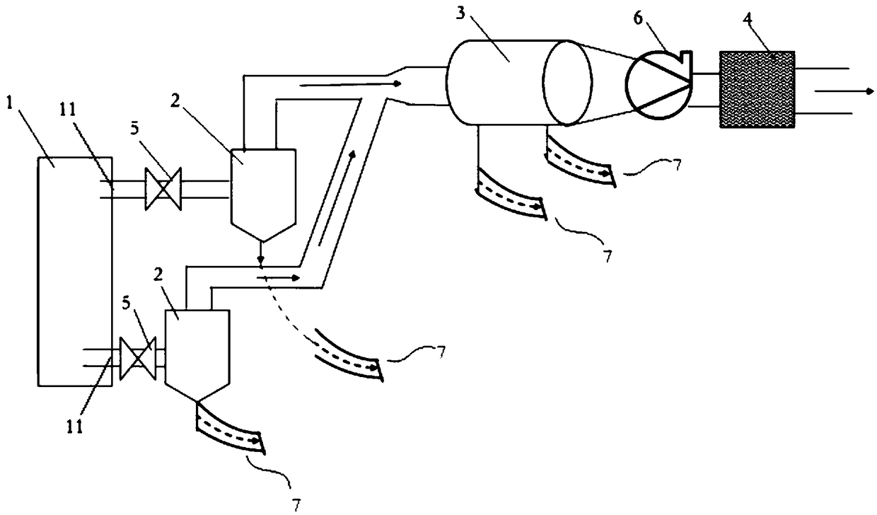
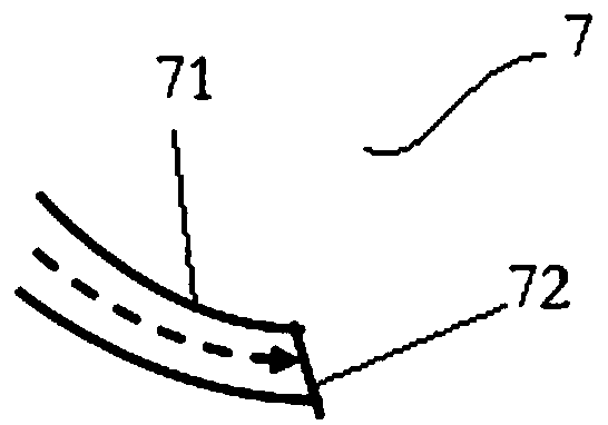
[0028] In one embodiment of the present invention, a paper machine wet end exhaust system is provided, see figure 1 , the system includes a paper machine wire section 1, an air extraction branch pipe, an air extraction main pipe and a blower fan 6, and the paper machine wire section 1 has one or more air outlets 11, and the air extraction branch pipe and the air outlet 11 one-to-one correspondence, figure 1 Only two air outlets 11 are shown in the figure, which are respectively located under the breast roll of the wire section of the paper machine and at the composite roll, but in actual application scenarios, the air outlet 11 may also be arranged under the headbox and tensioned At the roller place, etc., the outlet end of each air extraction branch pipe is connected with the inlet of the air extraction main pipe, and the outlet of the air extraction main pipe is connected with the exhaust fan 6, and the steam and water separation operation is performed by performing air extr...

Embodiment 2

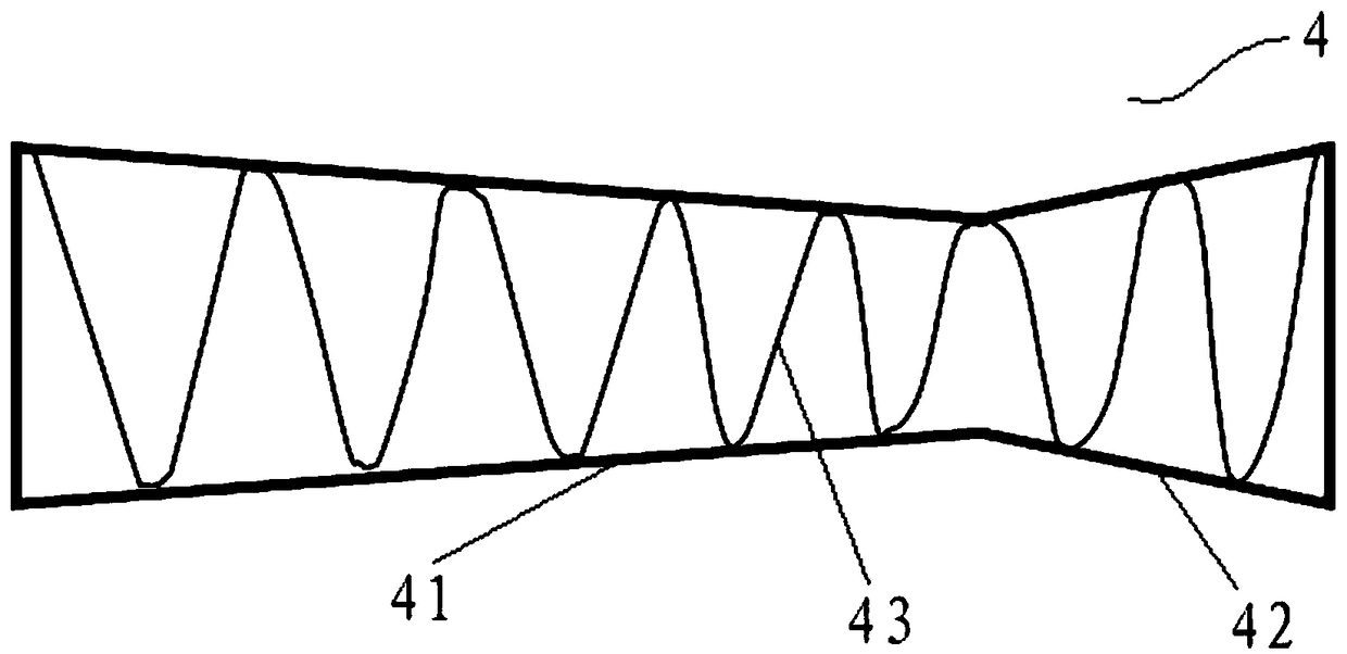
[0036] In another embodiment of the present invention, the fiber separation device 4 includes multiple layers of fiber separation plates arranged sequentially, see Figure 4 , as a preferred embodiment, the fiber separation device 4 includes a first fiber separation plate 44, a second fiber separation plate 45 and a third fiber separation plate 46, as can be seen from the figure, the first fiber separation plate 44 has a right Inclined air guide plate, the second fiber separation plate 45 has a horizontal air guide plate, and the third fiber separation plate 46 has a left-inclined air guide plate. Since adjacent fiber separation plates have wind guide structures in different directions, Therefore, the airflow passing through the fiber separation plate of the previous layer is guided again in the next layer. During the airflow guidance conversion process, the fiber impurities are kept in the fiber separation device 4 to the greatest extent to achieve the purpose of filtering. F...


PUM


Abstract

The invention discloses a paper machine wet part exhaust system. The paper machine wet part exhaust system comprises a paper machine net part, air exhaust branch pipes, an air exhaust main pipe and a fan, the paper machine net part is provided with one or more air exhaust outlets, the air exhaust branch pipes correspond to the air exhaust outlets in a one-to-one mode, the outlet end of each air exhaust branch pipe is communicated with an inlet of the air exhaust main pipe, and the outlet of the air exhaust main pipe is connected to an exhaust fan; each air exhaust main pipe is provided with a first vapor-water separator, the air exhaust main pipe is provided with a second vapor-water separator, and air locking devices are arranged below both the first vapor-water separators and the second first vapor-water separator. According to the paper machine wet part exhaust system, the air exhaust branch pipes / main pipe are built separately to conduct multi-layer vapor-water separation treatment, the exhaust air dryness is improved, the fan load is reduced, the operation stability is improved, the wet part air exhaust effect is improved, the field environment is improved, and the operation problem caused by slime pulp accumulated by water mists is avoided.

Description

technical field [0001] The invention relates to the field of papermaking, in particular to an exhaust system for the wet part of a paper machine. Background technique [0002] The wet end is a key part that determines the operation of the paper machine and the quality of the paper. The moisture generated in the wet end must be effectively discharged to avoid the accumulation of sludge and improve the operating environment. Humidity is sucked in order to discharge the moisture in the wet part. However, due to the high humidity of the pumped gas and the fiber contained in the water mist, the exhaust effect is poor, the fan failure is frequent, and the maintenance cost is high. At the same time, the moisture cannot be effectively discharged, resulting in large water mist inside and outside the rack It is easy to accumulate sludge, which reduces the operating efficiency of the paper machine. Contents of the invention [0003] In order to solve the problems of the prior art, ...

Claims


Application Information

Patent Timeline
Patent Type & Authority Patents(China)
IPC IPC(8): D21G9/00
CPCD21G9/00
Inventor 杨文恒刘玉国
Owner NINE DRAGONS PAPER TAICANG LTD
Learn More