
A sludge removal and drying device capable of performing two high-efficiency drying

A sludge and drying technology, applied in the direction of dehydration/drying/concentrated sludge treatment, etc., can solve the problems of waste of water resources, slow drying rate, pollution, etc., to increase absorption speed, increase contact degree, and improve drying speed effect

Active Publication Date: 2019-09-24
浙江河海建设有限公司
View PDF7 Cites 0 Cited by
  • Summary
  • Abstract
  • Description
  • Claims
  • Application Information

AI Technical Summary

Problems solved by technology

[0002] Sludge drying is the process of removing most of the water content from sludge through infiltration or evaporation. In the process of our sewage treatment, it is often accompanied by a large amount of sludge. If it is not treated effectively, it will be recycled again. It pollutes the environment. On the other hand, sludge is a special resource, which can be used as a resource after proper treatment. Whether it is from the perspective of transportation and disposal reduction and energy consumption reduction or from the perspective of agricultural necessary conditions, sludge drying It has become an important intermediate process of sludge resource utilization. The current sludge drying equipment generally has a slow drying rate and cannot complete the sludge drying process in a short time, resulting in secondary pollution, and some The sludge drying device lacks the treatment process for drying the humid air, not only the drying effect cannot meet the requirements, but also causes a waste of water resources, and even some sludge drying devices are due to the humid air during the drying process. Gradually increase, resulting in the effect of drying is not thorough enough to meet the standard of normal use

Method used


Image

  • A sludge removal and drying device capable of performing two high-efficiency drying
  • A sludge removal and drying device capable of performing two high-efficiency drying
  • A sludge removal and drying device capable of performing two high-efficiency drying

Examples


Embodiment Construction

[0015] The following will clearly and completely describe the technical solutions in the embodiments of the present invention with reference to the accompanying drawings in the embodiments of the present invention. Obviously, the described embodiments are only some of the embodiments of the present invention, not all of them. Based on the embodiments of the present invention, all other embodiments obtained by persons of ordinary skill in the art without making creative efforts belong to the protection scope of the present invention.

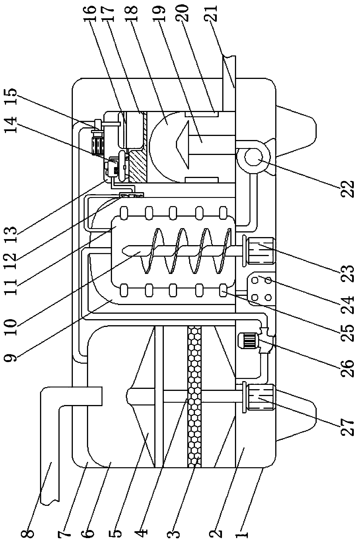
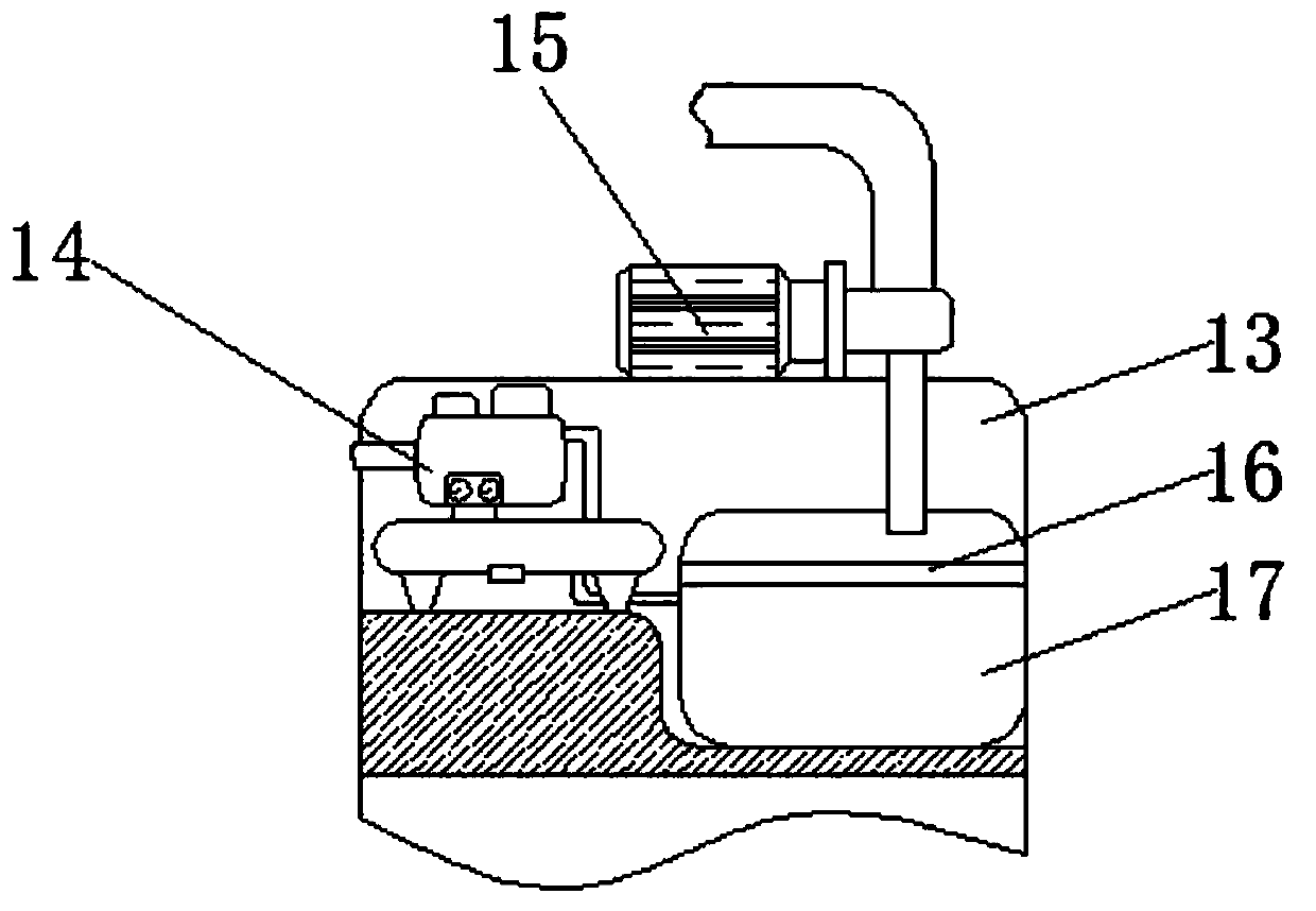
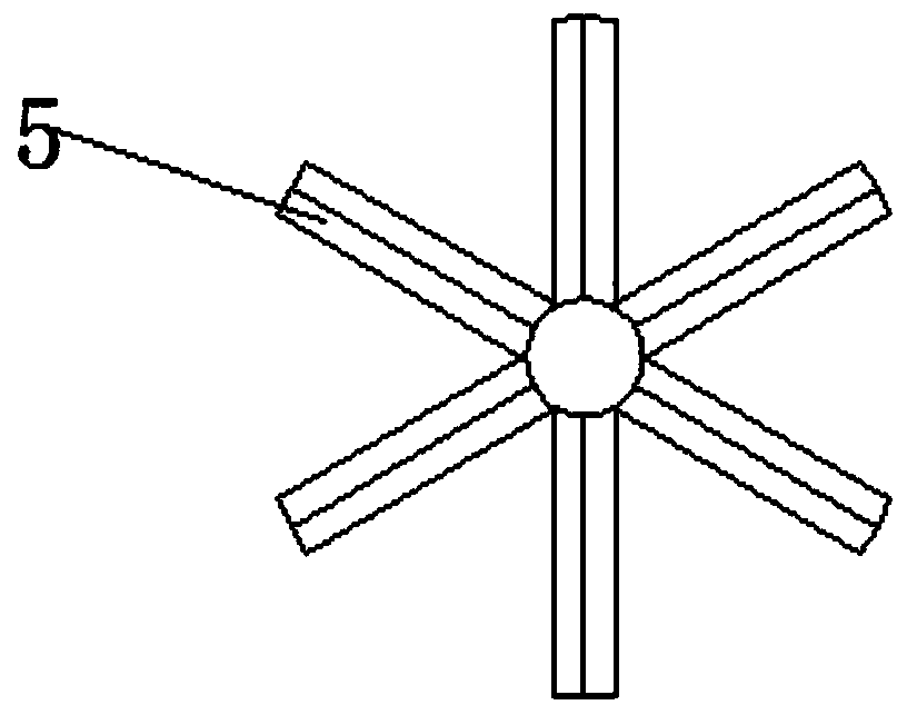
[0016] see Figure 1-4 , an embodiment provided by the present invention: a sludge removal and drying device that can perform two high-efficiency drying, including a body 1, an equipment room 2, a treatment room 7, a heat treatment chamber 9 and a condenser 14, and the inside of the body 1 An equipment room 2 is provided at the bottom of the equipment room 2, and a treatment chamber 7 is provided inside the body 1 above the equipment room 2. A fi...


PUM


Abstract

The invention discloses a sludge impurity-removing and drying device capable of performing efficient drying twice. The sludge impurity-removing and drying device comprises a machine body, anequipment chamber, a treatment chamber, a heat treatment chamber and a condenser, wherein the equipment chamber is formed in the bottom end of the inner part of the machine body; the treatment chamber is formed in the machine body above the equipment chamber; a filter chamber is formed in one end of the inner part of the treatment chamber; a sludge pipeline is mounted at a central position of the top end of the filter chamber; a rotating shaft is vertically mounted at the bottom end of the inner part of the filter chamber; a stirring paddle is mounted on the top of the rotating shaft; the heat treatment chamber is formed in the middle position of the inner part of the treatment chamber; a heating barrel is mounted inside the heat treatment chamber; a propeller is mounted at a central position of the inner part of the heating barrel; a recycling chamber is formed in one end, away from the filter chamber, of the inner part of the treatment chamber; a drying barrel is arranged at the bottom end of the inner part of the recycling chamber; a guiding body is mounted at the bottom end of the inner part of the drying barrel. The sludge impurity-removing and drying device not only increases the sludge drying speed, improves the sludge drying effect, and avoids waste of water resources.

Description

technical field [0001] The invention relates to the technical field of sludge removal and drying, in particular to a sludge removal and drying device capable of performing two times of high-efficiency drying. Background technique [0002] Sludge drying is the process of removing most of the water content from sludge through infiltration or evaporation. In the process of our sewage treatment, it is often accompanied by a large amount of sludge. If it is not treated effectively, it will be recycled again. It pollutes the environment. On the other hand, sludge is a special resource, which can be used as a resource after proper treatment. Whether it is from the perspective of transportation and disposal reduction and energy consumption reduction or from the perspective of agricultural necessary conditions, sludge drying It has become an important intermediate process of sludge resource utilization. The current sludge drying equipment generally has a slow drying rate and cannot c...

Claims


Application Information

Patent Timeline
Patent Type & Authority Patents(China)
IPC IPC(8): C02F11/13
Inventor 陈晓斌
Owner 浙江河海建设有限公司
Learn More