
Feeder convenient to adjust

A feeder, convenient technology, applied in the direction of conveyor objects, transportation and packaging, support frame, etc., can solve the problems of inconvenient alignment of the discharge pipe, inability to adjust multiple heights, and inability to rotate, etc., to achieve convenient alignment , Convenient feeding speed and stable feeding speed

Inactive Publication Date: 2017-07-21
TONGLING SANNUO ELECTRONICS
View PDF8 Cites 2 Cited by
  • Summary
  • Abstract
  • Description
  • Claims
  • Application Information

AI Technical Summary

Problems solved by technology

[0002] The feeder is a feeder in a general sense, but because of the different names in different places, different names have been produced, but its essence and function are basically the same. In the production process, materials need to be transferred from When the material is supplied evenly or quantitatively from the storage bin or other storage equipment to the material receiving equipment, the feeder comes into being. It is an essential equipment for the automation of assembly line operations. The feeder is suitable for bulk, Granular and powdery materials are evenly and continuously fed to the receiving device from the storage bin or hopper, and the materials are coarsely screened. It is widely used in metallurgy, coal mines, mineral processing, building materials, chemicals, abrasives and other industries. The existing feeding equipment cannot be adjusted at multiple heights, nor can it be rotated. It is inconvenient to feed materials at different heights, and it is also inconvenient to align the discharge pipe with the device being fed.

Method used


Image

  • Feeder convenient to adjust

Examples


Embodiment Construction

[0012] The following will clearly and completely describe the technical solutions in the embodiments of the present invention with reference to the accompanying drawings in the embodiments of the present invention. Obviously, the described embodiments are only some, not all, embodiments of the present invention. Based on the embodiments of the present invention, all other embodiments obtained by persons of ordinary skill in the art without making creative efforts belong to the protection scope of the present invention.

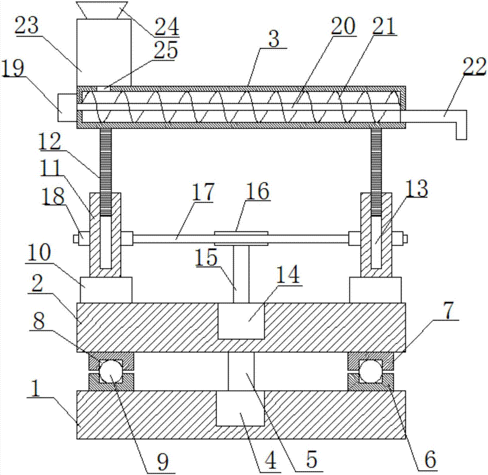
[0013] see figure 1 , in the embodiment of the present invention, a conveniently adjustable feeder includes a base 1, a support base 2 and a feeding pipeline 3, a first motor 4 is arranged in the middle of the upper side of the base 1, and the first motor 4 The output end is provided with a first rotating shaft 5, and the upper end of the first rotating shaft 5 is connected to the lower side of the support seat 2 in the middle, the upper side of the base 1 is ...


PUM


Abstract

The invention discloses a conveniently adjustable feeder, which comprises a base, a support base and a feeding pipeline. A first motor is arranged in the middle of the upper side of the base, and a first rotating shaft is arranged at the output end of the first motor. The upper end of the first rotating shaft It is connected with the lower side of the support seat in the middle, the upper side of the base is provided with a lower annular seat, the lower side of the support seat is provided with an upper annular seat, and the upper side of the lower annular seat and the lower side of the upper annular seat are symmetrically provided with annular chute , a number of balls are arranged in the annular chute, support rods are symmetrically arranged on the upper side of the support seat, a threaded rod is arranged on the upper end of the support rod, a second motor is arranged in the middle of the upper side of the support seat, and the output end of the second motor is arranged There is a second rotating shaft, the upper end of the second rotating shaft is provided with a driving wheel, the outer side of the supporting rod is provided with a driven wheel, the driving wheel and the driven wheel are connected by a belt, and the feeding pipe is arranged at the upper end of the threaded rod. The invention has the advantages of simple structure, convenient use, height adjustment, rotation alignment and stable feeding.

Description

technical field [0001] The invention relates to the technical field of feeding equipment, in particular to a conveniently adjustable feeding machine. Background technique [0002] The feeder is a feeder in a general sense, but because of the different names in different places, different names have been produced, but its essence and function are basically the same. In the production process, materials need to be transferred from When the material is supplied evenly or quantitatively from the storage bin or other storage equipment to the material receiving equipment, the feeder comes into being. It is an essential equipment for the automation of assembly line operations. The feeder is suitable for bulk, Granular and powdery materials are evenly and continuously fed to the receiving device from the storage bin or hopper, and the materials are coarsely screened. It is widely used in metallurgy, coal mines, mineral processing, building materials, chemicals, abrasives and other i...

Claims


Application Information

Patent Timeline
Patent Type & Authority Applications(China)
IPC IPC(8): B65G41/00
CPCB65G41/005
Inventor 章满权
Owner TONGLING SANNUO ELECTRONICS
Learn More