
Welding equipment for cell modules

A battery cell module and welding equipment technology, applied in welding equipment, resistance welding equipment, welding power supply, etc., can solve problems such as poor welding, welding wear of welding head, and false welding, so as to reduce damage or damage and improve production efficiency , Improve the effect of welding quality

Active Publication Date: 2017-07-21
深圳福源特新能源有限公司
View PDF8 Cites 17 Cited by
  • Summary
  • Abstract
  • Description
  • Claims
  • Application Information

AI Technical Summary

Problems solved by technology

The welding head is worn out, stolen or stuck with foreign matter, resulting in poor welding or even false welding

Method used


Image

  • Welding equipment for cell modules
  • Welding equipment for cell modules
  • Welding equipment for cell modules

Examples


Embodiment Construction

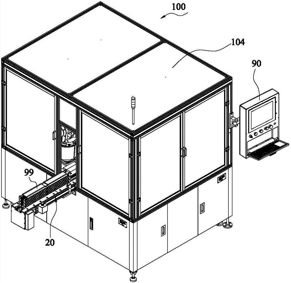
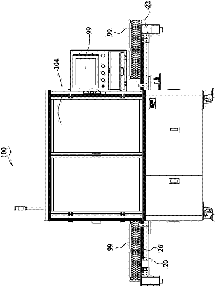
[0033] Such as Figure 1 to Figure 4 As shown, the battery module welding equipment 100 of an embodiment of the present invention includes: a frame 102, a conveying mechanism 20 arranged on the frame 102 to transport the workpiece to be processed, a welding mechanism 40 for welding the workpiece to be processed, a visual Position detection mechanism 60 and control system 90 . The conveying mechanism 20 includes: a feeding mechanism 22 for conveying the parts to be processed for feeding, and a cell module positioning mechanism 24 for receiving the parts to be processed conveyed by the feeding mechanism 22 and positioning the parts to be processed for positioning welding by the welding mechanism 40 .

[0034]The visual positioning detection mechanism 60 locates and finds the first welding spot on the workpiece to be processed, and uses the first welding spot as a reference point to find the relative coordinates of other welding spots. The control system 90 controls the welding...


PUM


Abstract

Welding equipment for cell modules comprises a rack, a conveying mechanism for conveying to-be-machined pieces, a welding mechanism, a visual positioning and detecting mechanism and a control system; the conveying mechanism comprises a feeding mechanism for conveying the to-be-machined pieces for feeding as well as a cell module positioning mechanism for positioning the to-be-machined pieces for positioning welding by the aid of the welding mechanism; the visual positioning and detecting mechanism positions and finds out first welding points on the to-be-machined pieces and determines relative coordinates of other welding points with the first welding points used as datum points; and the control system controls the welding mechanism to perform welding according to the relative coordinates. With the equipment, the first welding points of the workpieces are positioned and found out through the visual positioning and detecting mechanism and are used as the datum points for determining of the relative coordinates of other welding points, the welding mechanism is controlled to perform welding according to the relative coordinates, the coordinates of other welding points are convenient to determine for positioning welding, the feeding mechanism performs feeding automatically, and the cell module positioning mechanism positions the cell modules automatically, so that the positioning precision and the machining efficiency are improved.

Description

technical field [0001] The invention relates to the field of new energy battery manufacturing, in particular to a battery module welding equipment. Background technique [0002] In the production process of new energy battery packs, the most important process is the welding of the nickel sheet and the positive and negative electrodes of the circular battery. The most common welding method for this process is resistance welding. [0003] During the resistance welding process of battery pole pieces and nickel sheets, manual feeding is generally used. The product is manually placed on the equipment, the product is clamped and fixed, and then welded. After the welding is completed, the product is manually taken out. And in the process of resistance welding, there are several factors that are crucial to welding quality: welding discharge voltage, welding pressure and welding pin of welding head, which are basically not detected and controlled in the existing welding process. [...

Claims


Application Information

Patent Timeline
Patent Type & Authority Applications(China)
IPC IPC(8): B23K11/11B23K11/25B23K11/36H01M10/058H01R43/02
CPCH01M10/058H01R43/0214B23K11/002B23K11/11B23K11/25B23K11/36Y02E60/10Y02P70/50
Inventor 李枝成方万里王冠程
Owner 深圳福源特新能源有限公司
Learn More