An artificial reef made of urban construction waste

A technology for urban construction waste and artificial reefs, which is applied in the fields of application, climate change adaptation, fish farming, etc., can solve the problems of undisclosed applications, etc., and achieve the effects of simple structure, waste utilization of existing resources, and low cost.

Active Publication Date: 2019-11-15
宋宇
View PDF9 Cites 0 Cited by
  • Summary
  • Abstract
  • Description
  • Claims
  • Application Information

AI Technical Summary

Problems solved by technology

However, it does not disclose its application in marine farming

Method used


Image

  • An artificial reef made of urban construction waste
  • An artificial reef made of urban construction waste
  • An artificial reef made of urban construction waste

Examples


Embodiment 1

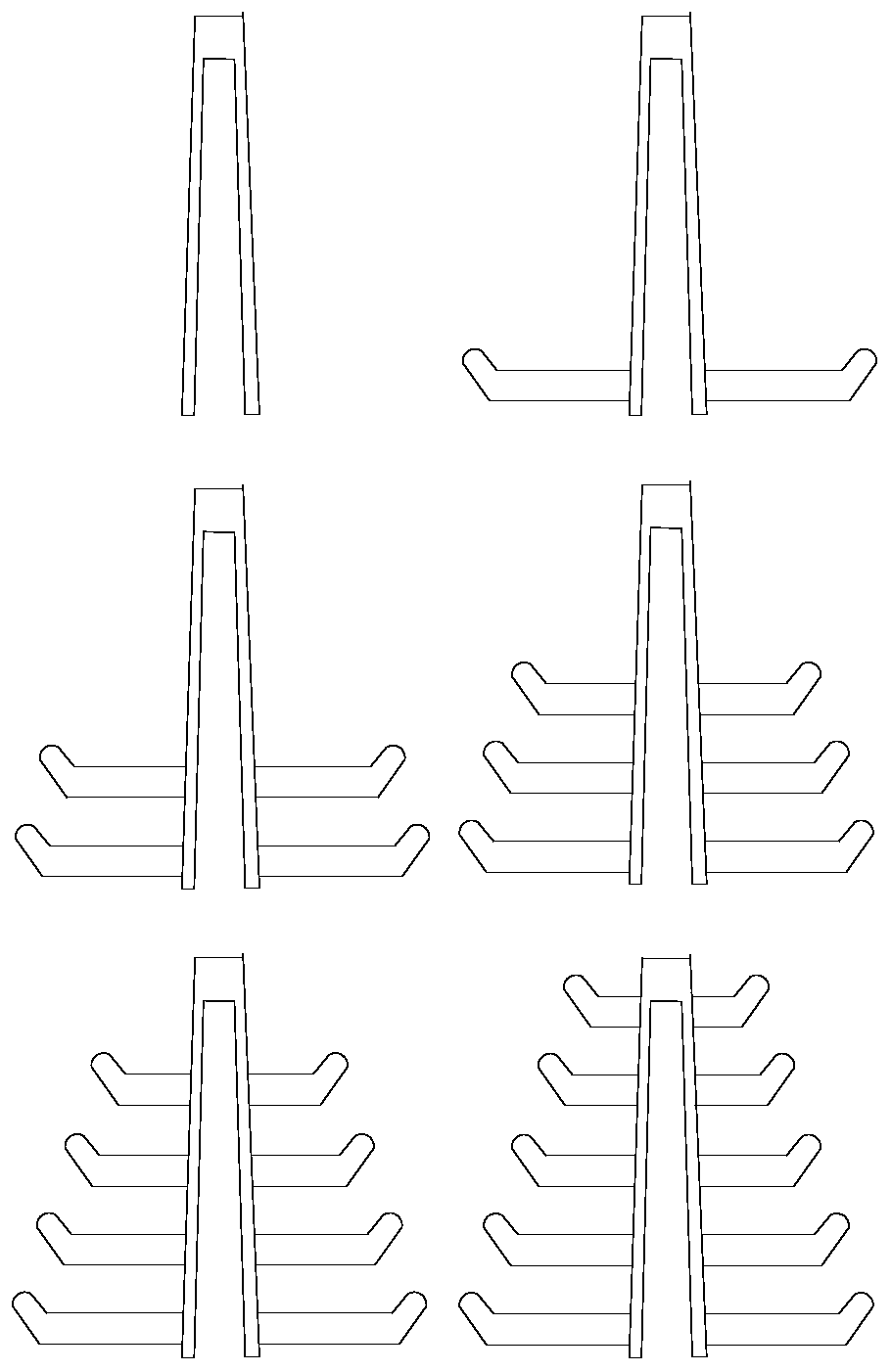
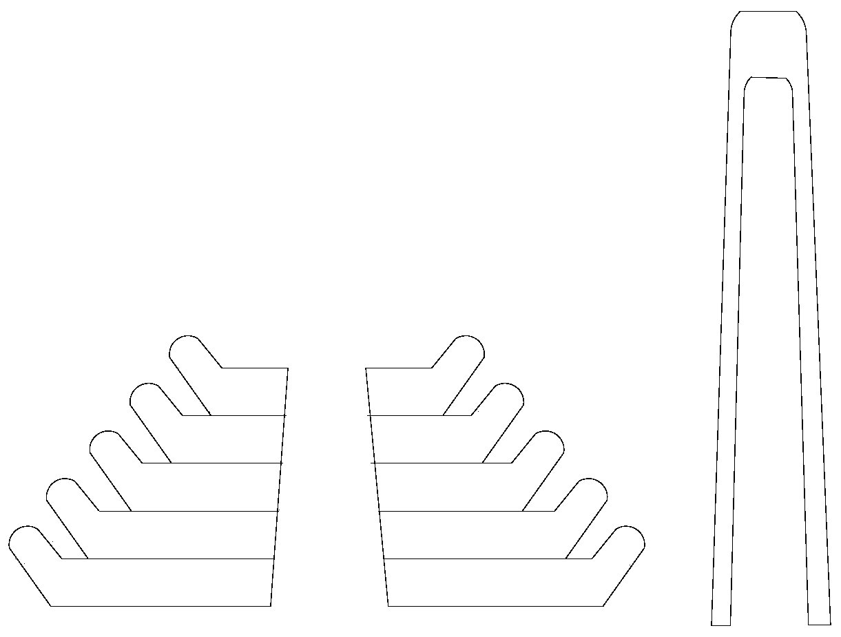
[0033] refer to figure 1 , the artificial reef provided in this embodiment includes concrete pillars 1 and five concrete reefs 2, wherein the cross-sectional size gradually increases from the top to the bottom of the concrete pillars 1, and the center of each concrete reef 2 There are socket holes 21 arranged in cooperation with the concrete pillars 1, and the concrete reefs 2 are sequentially arranged at intervals and socketed on the concrete pillars 1 through the respective socket holes 21; along the concrete The diameters of the concrete reefs 2 in the direction from the top to the bottom of the pillar 1 increase sequentially; each concrete reef 2 is provided with an edge portion 22 bent outward and upward; the concrete pillar 1 is a hollow rod, And the bottom end of the concrete pillar 1 is provided with an insertion opening 11, and the cross-sectional dimension of the insertion opening 11 is larger than the cross-sectional dimension of the top end of the concrete pillar 1...

Embodiment 2

[0038] like Figure 5-7 As shown, compared with the artificial reef provided in the present embodiment 1, the artificial reef provided in the present embodiment is different in that: the end of the concrete reef plate 2 near the socket hole 21 is provided with an installation groove 23, the The installation groove 23 communicates with the sleeve hole 21 and is set through the bottom of the concrete reef 2; the concrete pillar 1 is provided with an installation hole 13 corresponding to each of the concrete reef 2, and the artificial reef It also includes a fixing rod 3 that is threadedly connected with the installation hole 13 and matched with the sleeve hole 21 .

[0039]Both the concrete pillar and the artificial reef are made of recycled foamed concrete, and the mold is made of glass fiber, which makes the present invention high in strength, low in cost, and saves resources by utilizing waste; Seawater erosion experiments enable the present invention to be used normally in ...


PUM


Abstract

The invention discloses an artificial reef which comprises a concrete supporting column and a plurality of concrete reef plate bodies. The cross section size of the concrete supporting column from the top end to the bottom end is gradually increased, a sleeved connection hole matched with the concrete supporting column in arrangement is formed in the center of each concrete reef plate body in a penetrating mode, the concrete reef plate bodies are sequentially arranged at intervals and are in sleeved connection with the concrete supporting column through respective sleeved connection holes. When the artificial reef is used, the concrete supporting column is firstly placed, and then the concrete reef plate bodies are sequentially placed from the top end of the concrete supporting column. During transportation, each artificial reef serves as one unit for transportation, or the same spare parts are transported together, cushion woods are placed among all layers of spare parts to prevent jolting and bumping. Therefore, the artificial reef has the advantages of being simple in structure, simple in installing process and convenient to transport. The artificial reef is manufactured by using the urban construction waste as raw materials and performing regeneration foaming to form regenerated foaming concrete, achieves the effects of utilizing waste and saving existing resources and is low in manufacturing cost.

Description

technical field [0001] The invention relates to the technical field of aquaculture, in particular to an artificial reef made of urban construction waste. Background technique [0002] With the development of socio-economic technology and contemporary high-tech, the contemporary construction industry is in full swing. Many old buildings are gradually replaced by new high-rise buildings. At the same time, due to economic development and the accelerated upgrading of the construction industry, A large amount of garbage generated when many old buildings are demolished has nowhere to be piled up, so the adverse impact on the urban environment has become increasingly prominent. It is imperative to use existing technology to recycle the existing construction waste, which can save resources and be environmentally friendly. Beautify. [0003] Equally important issues that need to be resolved are marine ecological issues. In recent years, as countries have rushed to develop industries...

Claims


Application Information

Patent Timeline
Patent Type & Authority Patents(China)
IPC IPC(8): A01K61/70
CPCY02A40/81
Inventor 宋宇
Owner 宋宇
Why Eureka
Try Eureka