
Pulsed excitation-based dynamic thermal chromatography imaging detection system and method

An imaging detection and pulse excitation technology, which is applied in the field of dynamic thermal tomography detection systems based on pulse excitation, can solve the problems of insensitive detection of defects in the surface layer and superficial layer of materials, and inability to form a three-dimensional geometric shape of material defects, reducing the The effect of lateral thermal diffusion, efficient detection, and improved detection signal-to-noise ratio

Inactive Publication Date: 2017-07-18
HARBIN INST OF TECH
View PDF3 Cites 15 Cited by
  • Summary
  • Abstract
  • Description
  • Claims
  • Application Information

AI Technical Summary

Problems solved by technology

[0003] The purpose of the present invention is to overcome the problem that the traditional non-destructive testing method in the prior art is not sensitive to the detection of material surface and shallow surface defects and cannot form the three-dimensional geometric shape of material defects, and provides a dynamic thermal tomography based on pulse excitation Imaging detection system and method

Method used


Image

  • Pulsed excitation-based dynamic thermal chromatography imaging detection system and method
  • Pulsed excitation-based dynamic thermal chromatography imaging detection system and method
  • Pulsed excitation-based dynamic thermal chromatography imaging detection system and method

Examples


specific Embodiment approach 1

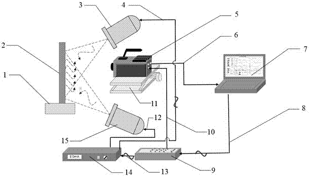
[0033] Specific implementation mode 1: This implementation mode records a dynamic thermal tomography detection system based on pulse excitation (such as figure 1 shown), the system includes a three-dimensional mobile platform 1, a test sample 2, a first xenon lamp 3, a power cord 4 for the first xenon lamp, an infrared thermal imager 5, an Ethernet cable 6, a computer 7, a USB data cable 8, and data acquisition Card (with arbitrary function generation function) 9, BNC trigger signal line 10, vertical lifting platform 11, second xenon lamp power line 12, BNC data line 13, xenon lamp power supply 14, second xenon lamp 15;

[0034] The signal output end of the infrared thermal imager 5 is connected with the signal input end of the computer 7 through the Ethernet line 6, and the signal output end of the computer 7 is connected with the signal input end of the data acquisition card 9 through the USB data line 8, and the data acquisition Card 9 signal output terminal one is connecte...

specific Embodiment approach 2

[0035] Embodiment 2: A method for realizing dynamic thermal tomography detection based on pulse excitation by using the system described in Embodiment 1. The specific steps of the method are as follows:

[0036] Step 1: Determine the test sample 2 to be measured, and place it on the three-dimensional mobile platform 1;

[0037] Step 2: Turn on the dynamic thermal tomography detection system based on pulse excitation. This step includes turning on the computer 7, the data acquisition card 9, the xenon lamp power supply 14 and the thermal imaging camera 5;

[0038] Step 3: Correct the non-uniformity of the infrared thermal imager 5, and then use the computer 7 to control the software to assist the infrared thermal imager 5 to adjust the imaging detection field of view, and adjust the three-dimensional mobile station 1 to make the image clear;

[0039] Step 4: The computer 7 controls the data acquisition card 9 and then controls the xenon lamp power supply 14, and then controls t...


PUM


Abstract

The invention discloses a pulsed excitation-based dynamic thermal chromatography imaging detection system and method and belongs to the technical field of imaging detection. The system comprises a mobile station, a first xenon lamp, a first xenon lamp power line, a thermal infrared imager, an Ethernet cable, a computer, a USB data line, a data collection card, a BNC trigger signal line, a vertical lifting platform, a second xenon lamp power line, a BNC data line, a xenon lamp power supply and a second xenon lamp. The pulsed excitation-based dynamic thermal chromatography imaging detection system and method have the advantages that non-destructive and non-contact efficient detection of defects of surfaces and shallow surfaces of a composite material, a metal material, an inorganic nonmetallic material and a synthetic material can be achieved, and meanwhile, the system and the method are not limited by the size of a detected material; lateral heat diffusion of heat flow can be relatively well reduced, thereby improving the signal-to-noise ratio (lightweight) of defect detection; by adopting the xenon lamps as light sources, short-time high power (time 1 / 600s and short-time peak power 4,000W) injection of energy can be ensured; and three-dimensional reconstruction of material defects can be achieved.

Description

technical field [0001] The invention belongs to the technical field of imaging detection, and in particular relates to a dynamic thermal tomography detection system and method based on pulse excitation. Background technique [0002] With the rapid development of the national economy, a series of new materials are constantly emerging in the industrial field, and the high quality assurance of new materials plays a vital role in the development of the entire industry. Composite materials are prone to defects such as debonding, pores, and bulges during the processing process and subsequent use. Metal materials are prone to surface cracks, internal pores, and internal stress. These defects seriously threaten the performance of the final product. Because the processing technology of new materials is different from that of traditional materials, some traditional and mature processing technologies are no longer suitable for the production of new materials, so it is necessary to prov...

Claims


Application Information

Patent Timeline
IPC IPC(8): G01N25/72
CPCG01N25/72
Inventor 刘俊岩王飞宋鹏冀嘉琦林裕山王扬
Owner HARBIN INST OF TECH
Learn More