Laser cutting film sticking machine and utilization method thereof

A laser cutting and film laminating machine technology, which is applied in laser welding equipment, manufacturing tools, welding equipment, etc., can solve the problems that a single film can not adapt to multiple processes, the equipment occupies a large area, and the degree of automation is low. The effect of small area, fast cutting speed and strong maneuverability

Inactive Publication Date: 2017-07-18
苏州斯克纳自动化设备有限公司
View PDF6 Cites 7 Cited by
  • Summary
  • Abstract
  • Description
  • Claims
  • Application Information

AI Technical Summary

Problems solved by technology

Although the existing film laminating machines can basically realize the protection of products, they have the following defects: 1) low degree of automation, low efficiency, unreasonable structure and large equipment footprint; 2) single film lamination cannot adapt to multiple processes, each The manufacturing process needs to formulate films of different shapes; 3) Since each film must have a base film, the cost of film sticking is very high

Method used


Image

  • Laser cutting film sticking machine and utilization method thereof
  • Laser cutting film sticking machine and utilization method thereof
  • Laser cutting film sticking machine and utilization method thereof

Examples


Embodiment Construction

[0027] The present invention will be described in detail below in conjunction with the accompanying drawings and embodiments.

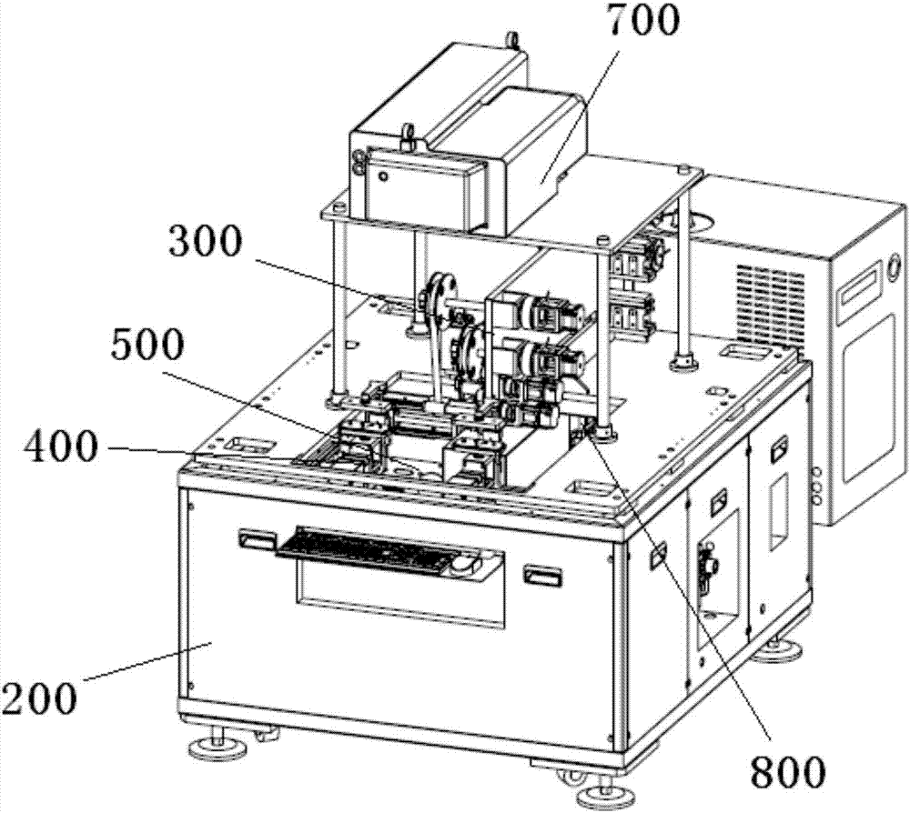
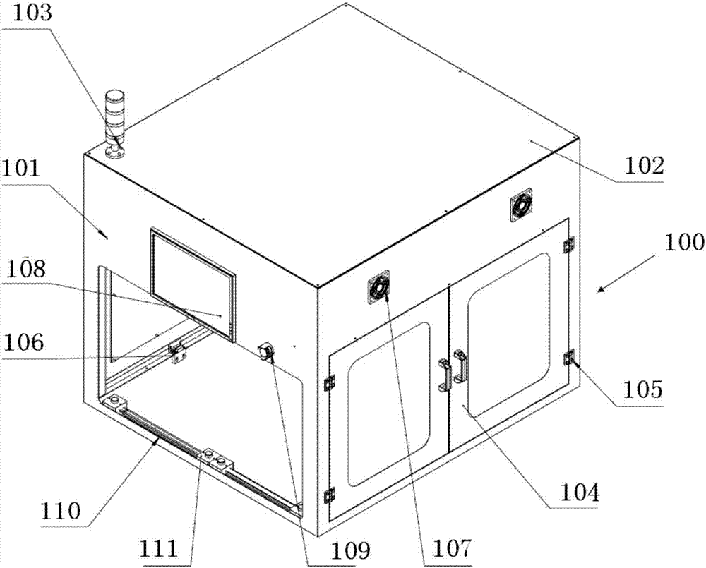
[0028] Such as figure 1 , figure 2 As shown, the present invention provides a laser cutting and film laminating machine, which is mainly used in the production and assembly fields of electronic industries such as mobile phones, to protect the frame of mobile phones and prevent damage to the frames of electronic products such as mobile phones during production and assembly. The present invention includes an upper frame mechanism 100 , a lower frame mechanism 200 , a film roll mechanism 300 , a motion mechanism 400 , a rotation mechanism 500 , a clamp mechanism 600 , a laser mechanism 700 and a control mechanism 800 . The upper frame mechanism 100 is fixed on the upper part of the lower frame mechanism 200 by bolts, the film rolling mechanism 300, the moving mechanism 400, the rotating mechanism 500, the clamp mechanism 600 and the laser mechanism 700...


PUM


Abstract

The invention relates to a laser cutting film sticking machine and a utilization method thereof. The laser cutting film sticking machine comprises an upper frame mechanism, a lower frame mechanism, a film rolling mechanism, a motion mechanism, a rotating mechanism, a fixture mechanism, a laser mechanism and a control mechanism, wherein the upper frame mechanism is fixed to the upper part of the lower frame mechanism through bolts; the film rolling mechanism is above the motion mechanism; the rotating mechanism is fixed to the motion mechanism; the fixture mechanism is connected with the rotating mechanism; the laser mechanism is arranged above the film rolling mechanism; the control mechanism used for controlling the entire film sticking machine to operate is further arranged in the lower frame mechanism; the lower frame mechanism comprises a lower frame; a bottom plate is arranged at the top of the lower frame; a mounting hole is formed in the bottom plate; a laser mounting plate is mounted above the bottom plate through laser struts; protective plates are arranged on the four side surfaces of the lower frame; a keyboard mouse connected with the control mechanism is arranged on the protective plate at the front part; an air source processor and a load switch are arranged on the protective plate on the right side of the lower frame; foot cups are arranged at the bottom of the lower frame; and the control mechanism is arranged on the inner back side of the lower frame. According to the laser cutting film sticking machine, structure is compact, floor space is small, and curvilinear motion of a product during the film sticking process can be achieved.

Description

technical field [0001] The present invention relates to an automatic equipment and its use method, in particular to a laser cutting and laminating machine used in the fields of production and assembly in the electronics industry and its use method. Background technique [0002] With the increasing popularity of mobile phones and other electronic products, the technical requirements for the production of mobile phones and other electronic products are getting higher and higher and more refined; therefore, higher requirements are put forward for manufacturers of mobile phones and other electronic products: in improving the quality of products while reducing costs. In this way, in the production process of electronic products such as mobile phones, it is necessary to cause damage to the products as much as possible; especially in the later stages of the production process, all the processes before the damage to a product are all in vain. Therefore, the film laminating machine ...

Claims


Application Information

Patent Timeline
Patent Type & Authority Applications(China)
IPC IPC(8): B23K26/38B23K26/40B23K26/08B29C63/02
CPCB23K26/0846B23K26/142B23K26/38B23K26/402B29C63/02
Inventor 陈杰
Owner 苏州斯克纳自动化设备有限公司
Why Eureka
Try Eureka