
Heat exchanger for power-electronic components

A technology of power electronic modules and heat exchangers, which is applied in the direction of indirect heat exchangers, electrical equipment structural parts, electrical components, etc., can solve the problems of restricting two-phase cooling systems, improve reliability and life, reduce weight, Effect of reducing filter size

Active Publication Date: 2017-07-14
ABB (SCHWEIZ) AG
View PDF7 Cites 3 Cited by
  • Summary
  • Abstract
  • Description
  • Claims
  • Application Information

AI Technical Summary

Problems solved by technology

[0006] However, cost considerations and the challenging process of integrating and orienting two-phase systems into power electronics systems restrict the application of two-phase cooling systems in power electronics systems

Method used


Image

  • Heat exchanger for power-electronic components
  • Heat exchanger for power-electronic components
  • Heat exchanger for power-electronic components

Examples


Embodiment Construction

[0050] In the following, various aspects and embodiments of the invention are described. It is intended that each aspect, whether or not described in the context of a particular embodiment or other feature, can be combined with any other aspect.

[0051] In the drawings and the following description, the same reference numerals are used for similar elements, and descriptions of any embodiment with respect to the same reference numerals are applicable to any other embodiment unless mentioned otherwise, and / Or unless the description would be inconsistent with this embodiment.

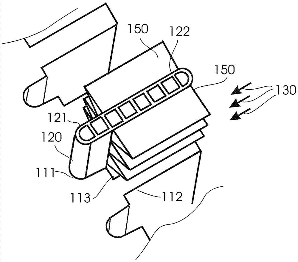
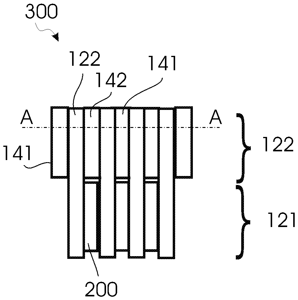
[0052] figure 1 A two-phase heat exchanger arrangement 100 is shown according to embodiments described herein. The heat exchanger device 100 is in figure 1 exemplarily shown as being stacked between two semiconductor modules 201 and 202 . Typically, if able to figure 1 Seen on the coordinate system in , the heat exchanger device 100 and the two semiconductor modules 201 , 202 are stacked along the s...


PUM


Abstract

It is proposed a two-phase heat exchanger device (100) for a power-electronic module arrangement having a semiconductor module. The two-phase heat exchanger device includes a base plate (110) configured for being in contact with a first semiconductor module (201) at a first side (123) of the base plate; and at least one tube element (120) for a first cooling medium (131) including a first portion (121) having at least one evaporator channel and a second portion (122) having at least one condenser channel. The base plate has a groove (111; 112) containing the tube element, wherein the groove is dimensioned for enabling thermal contact between the base plate and the first portion of the tube element and dimensioned to form a gap (113) between the base plate and the second portion of the tube element for thermal separation of the base plate and the second portion of the tube element.

Description

technical field [0001] The present invention generally relates to heat exchangers. In particular, the invention relates to heat exchangers that can be used in power electronic components. The invention further relates to a power electronics module assembly comprising a heat exchanger. Background technique [0002] In a typical power electronic system, power electronic components such as discrete or integrated (ie, modular) semiconductor devices, inductors, resistors, capacitors, and copper bus bars are packed in close proximity. In all designs, there is the same PCB panel and electronic controls. During operation, these components dissipate different amounts of heat. Additionally, these components are subject to different levels of temperature. The thermal management and integration concept of the drive system must take into account the temperature ranges that occur. [0003] For power electronics (PE) systems in the low and medium power range, air cooling is a commonly...

Claims


Application Information

Patent Timeline
Patent Type & Authority Applications(China)
IPC IPC(8): H05K7/20
CPCH05K7/20136H05K7/20309H05K7/20318F28D15/0233F28D15/0266F28D15/0275F28F1/022F28F13/00F28F2270/00F28F2275/02H05K7/20336H05K7/20936H05K7/20327
Inventor D.托雷斯恩B.阿戈斯蒂尼F.阿戈斯蒂尼T.格拉丁格M.哈伯特
Owner ABB (SCHWEIZ) AG
Learn More