Buck converter synchronization rectification drive circuit and control method
A technology of synchronous rectification and drive circuit, applied in electrical components, output power conversion devices, etc., can solve problems such as damage to synchronous rectifier tubes, and achieve the effects of improving reliability, solving damage problems, and reducing size
- Summary
- Abstract
- Description
- Claims
- Application Information
AI Technical Summary
Problems solved by technology
Method used
Image
Examples
no. 1 example
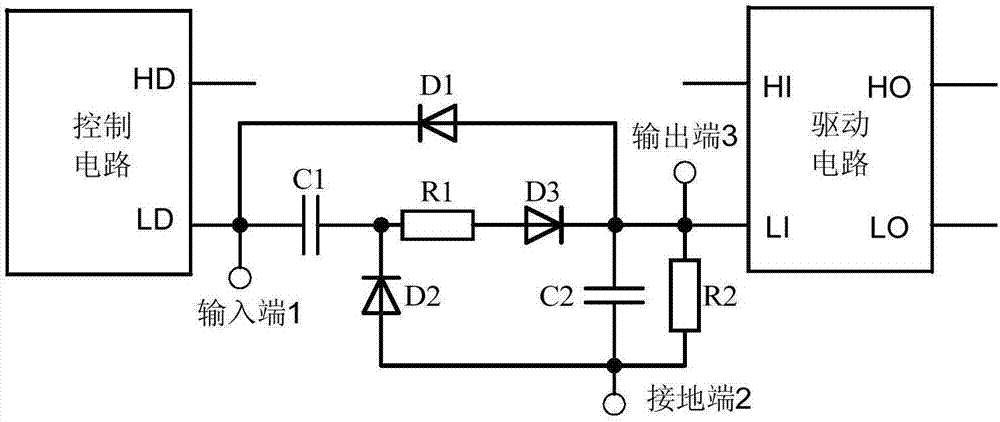
[0038] Such as image 3 Shown is the schematic diagram of the first embodiment, a step-down converter synchronous rectification drive circuit, characterized in that it includes a control circuit, a drive circuit and a synchronous rectification control signal adjustment circuit, and the output end of the control circuit is connected to the synchronous The input end of the rectification control signal adjustment circuit, the output end of the synchronous rectification control signal adjustment circuit is connected to the input end of the drive circuit; the synchronous rectification control signal adjustment circuit includes: input end 1, ground end 2, output end 3 and capacitor C1 , capacitor C2, resistor R1, resistor R2, diode D1, diode D2, and diode D3; one end of the capacitor C1 is connected to the input terminal 1, and the other end is connected to the cathode of the diode D2; the anode of the diode D2 Connect the ground terminal 2; one end of the resistor R1 is connected t...
no. 2 example
[0052] Such as Figure 4 Shown is the schematic diagram of the second embodiment, a step-down converter synchronous rectification drive circuit, characterized in that it includes a control circuit, a drive circuit and a synchronous rectification control signal adjustment circuit, and the output end of the control circuit is connected to the synchronous The input end of the rectification control signal adjustment circuit, the output end of the synchronous rectification control signal adjustment circuit is connected to the input end of the drive circuit; the synchronous rectification control signal adjustment circuit includes: input end 1, ground end 2, output end 3 and capacitor C1 , capacitor C2, resistor R1, resistor R2, diode D1, diode D2, and diode D3; one end of the capacitor C1 is connected to the input terminal 1, and the other end is connected to the cathode of the diode D2; the anode of the diode D2 connected to the ground terminal 2; one end of the resistor R1 is conn...
PUM
 Abstract
Description
Claims
Application Information
 - R&D Engineer
- R&D Manager
- IP Professional
- Industry Leading Data Capabilities
- Powerful AI technology
- Patent DNA Extraction
Browse by: Latest US Patents, China's latest patents, Technical Efficacy Thesaurus, Application Domain, Technology Topic, Popular Technical Reports.
© 2024 PatSnap. All rights reserved.Legal|Privacy policy|Modern Slavery Act Transparency Statement|Sitemap|About US| Contact US: help@patsnap.com


