An insulating pull rod assembly

A technology of insulating pull rods and components, applied in the direction of electrical components, contact operating parts, emergency protection devices, etc., can solve problems such as unsatisfactory insulation performance, limit the development trend of switchgear, large and bulky ceramic insulation structure of insulating pull rods, etc., to achieve Novel concept, not easy to fall off, firm and accurate installation

Active Publication Date: 2019-12-03
河南基泰电气有限公司
View PDF6 Cites 0 Cited by
  • Summary
  • Abstract
  • Description
  • Claims
  • Application Information

AI Technical Summary

Problems solved by technology

[0002]In the prior art, the insulating pull rods used in various switchgears are mainly made of ceramic insulating structures, which are too bulky and bulky, with threaded connections at both ends, requiring special tooling , the insulation performance is not ideal, and as the switchgear becomes more and more miniaturized, the existing insulating rods have limited the development trend of the switchgear

Method used


Image

  • An insulating pull rod assembly
  • An insulating pull rod assembly
  • An insulating pull rod assembly

Examples


Embodiment Construction

[0022] The technical solutions of the present invention will be further described in detail below in conjunction with the accompanying drawings and embodiments.

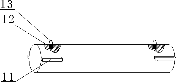
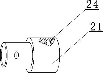
[0023] Such as figure 1 As shown, an insulating tie rod assembly includes an inner joint, an outer joint, and an insulating tie rod 1; two inserts 11 are respectively arranged on the circumferential outer walls of the left and right ends of the insulating tie rod 1, and the two inserts 11 are arranged symmetrically. 1 The upper ends of the outer walls of the left and right ends are respectively provided with installation grooves, and a spring 12 is fixed in the installation groove, and a positioning block 13 is fixedly connected to the upper end of the spring 12; one end of the inner joint is provided with an installation sleeve 21, and the installation sleeve 21 is open at one end The hollow structure of the installation sleeve 21 is provided with two symmetrical slots 25 on the inner side wall of the installation s...


PUM


Abstract

The present invention discloses an insulation pull bar assembly comprising an inner joint, an outer joint and an insulation pull bar. The circumferential outside walls of the left and right ends of the insulation pull bar are provided with two insertion blocks respectively, the two insertion blocks are symmetrically arranged, upper ends of the outside walls of the left and right ends of the insulation pull bar are provided with an installation groove respectively, each insulation groove is internally fixedly provided with a sprig, and the upper end of each spring is fixedly connected with a positioning block. One end of the inner joint is provided with an installation sleeve, one end of the installation sleeve is a hollow structure with one end opened, the inside wall of the installation sleeve is provided with two symmetric insertion grooves, the upper end of the inside wall of the installation sleeve is provided with a positioning groove, the two insertion blocks of the left end of the installation pull bar are inserted into the insertion grooves in one-to-one correspondence, and the positioning block of the left end of the insulation pull bar is installed in the positioning groove of the installation sleeve. The inner joint and the outer joint have the same structure. The right end part of the insulation pull bar is installed in the installation sleeve on the outer joint.

Description

technical field [0001] The invention belongs to the technical field of electrical equipment, and in particular relates to an insulating pull rod assembly. Background technique [0002] In the prior art, the insulating pull rods used in various switchgears are mainly made of ceramic insulating structures, which are too bulky and bulky, with screw connections at both ends, requiring special tooling, and the insulation performance is not ideal. As the switchgears become smaller and smaller The existing insulating rods have limited the development trend of switchgear. Contents of the invention [0003] In order to solve the problems existing in the background technology, the object of the present invention is to provide an insulating pull rod assembly, which can be installed quickly and accurately and connected reliably. [0004] In order to realize the above-mentioned purpose of the invention, the present invention adopts the technical scheme as follows: [0005] An insulat...

Claims


Application Information

Patent Timeline
Patent Type & Authority Patents(China)
IPC IPC(8): H01H3/02
CPCH01H3/02H01H2300/056
Inventor 王志方
Owner 河南基泰电气有限公司
Why Eureka
Try Eureka