
Test wiring wire clamp

A technology for testing wiring and clamps, which is applied in the direction of instruments, measuring devices, and parts of electrical measuring instruments. It can solve problems such as poor contact, unsatisfactory work requirements, and many test clamps, so as to ensure standardization and normalization. Improving the efficiency of on-site operations and improving the quality of work

Inactive Publication Date: 2017-07-14
STATE GRID CORP OF CHINA +1
View PDF5 Cites 2 Cited by
  • Summary
  • Abstract
  • Description
  • Claims
  • Application Information

AI Technical Summary

Problems solved by technology

These two methods have the following defects: For the whole bare copper wire winding short-circuit method, this wiring method has disadvantages such as poor contact, cumbersome connection and disassembly, and does not meet the working requirements of the "Electric Safety Regulations" test wiring; Wire series short connection method, this wiring method has many problems such as messy wires, many test wire clamps, time-consuming connection and disconnection, and low efficiency
[0004] Moreover, the current test clamps are all single-ended clamps, which cannot effectively connect the device under test to the short wire for testing.

Method used


Image

  • Test wiring wire clamp
  • Test wiring wire clamp
  • Test wiring wire clamp

Examples


Embodiment 2

[0028] Embodiment 2 of the present invention differs from Embodiment 1 only in that an insulating protective cover is provided on the outside of the handle of the first wire clip, the outside of the handle of the second wire clip and the outside of the shared handle to prevent the user from Electric shock during use improves the safety factor of users.

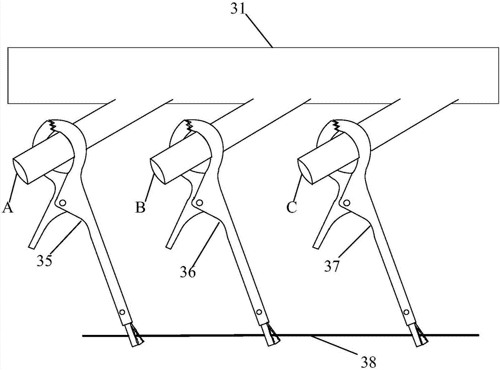
[0029] Embodiment 3 of the present invention, as image 3 As shown, the specific usage scenarios of the test wiring clip are provided.

[0030] Concretely, prepare the test wiring clamp 35, the test wiring clamp 36 and the test wiring clamp 37, the first clamps of the three test wiring clamps are all battery clips, and the second clamps are all button type alligator clips. The dimensions of the three test wiring clips are: length 130mm, width 50mm, height 10mm; the maximum opening size of the battery clip is 20mm, and the bite depth is 25mm; the maximum opening size of the button-type crocodile clip is 10mm, The depth of the...


PUM


Abstract

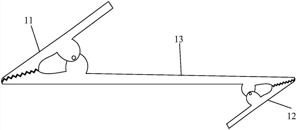
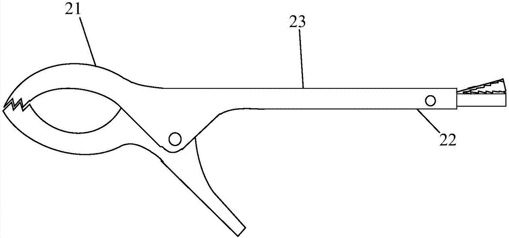
The present invention provides a test wiring clamp, comprising: a first clamp and a second clamp; wherein, the first clamp and the second clamp have a common handle, and the first clamp and the The second wire clips are respectively located at two ends of the common clip handle. The new type of double-ended test wiring clip provided by the invention, the clips at both ends share a common clamping handle, which replaces the design structure of the traditional single-ended cable clip, enhances the product performance of the cable clip, reduces the number of test wiring, and solves the problem of testing In the wiring process, there are many problems such as the use of multiple wire clips and the cumbersome wiring and disconnection process, which greatly improves the efficiency of on-site operations, improves the quality of work, and ensures the standardization and normalization of the operation process.

Description

technical field [0001] The invention relates to the field of electric power testing, more specifically, to a test wiring clip. Background technique [0002] The test clamp is a commonly used tool in the high-voltage test link of the electric power industry. It is widely used in the test short-circuit connection link, with a large number of uses and a high frequency of application. [0003] At present, two methods are usually used when short-circuiting the main transformer circuit breaker, universal circuit breaker and other tested equipment on site: one is the whole bare copper wire winding short circuit method, and the other is multiple wire series short circuit method. These two methods have the following defects: For the whole bare copper wire winding short-circuit method, this wiring method has disadvantages such as poor contact, cumbersome connection and disassembly, and does not meet the working requirements of the "Electrical Safety Regulations" test wiring; Wire ser...

Claims


Application Information

Patent Timeline
Patent Type & Authority Applications(China)
IPC IPC(8): G01R1/04
CPCG01R1/0425
Inventor 李毅郭述友沈祖成邓业刚严显玉芦程张扬米小军聂云李亚琼罗湘慈吴丹姜铭皮庆李一哲踪红飞朱苗甘甜孙林张勇余海东周清谢忠华包宗士
Owner STATE GRID CORP OF CHINA
Learn More