
Refuse landfill leachate guide and drainage pipe dredging device

A technology for landfill and leachate, applied in water supply installations, cleaning sewer pipes, waterway systems, etc., can solve the problems of easy residues of small substances, pollution of surrounding residents' domestic water, blockage, etc.

Pending Publication Date: 2017-07-14
SHENZHEN GAD ENVIRONMENTAL TECH
View PDF6 Cites 6 Cited by
  • Summary
  • Abstract
  • Description
  • Claims
  • Application Information

AI Technical Summary

Problems solved by technology

However, when passing through the flower hole and entering the leachate drainage pipe, fine material residues tend to remain on the edge of the flower hole, and microorganisms adhere to the surface of the leachate drainage pipe and secrete viscous substances such as extracellular polysaccharides. Main, covers the flower hole, eventually causing the flower hole to be blocked
In addition, some fine material residues enter the flower tube smoothly, and the leachate will drive some fine material residues to flow out, but some of them remain in the flower tube. If things go on like this, the flower tube can reduce the cross-sectional area of ​​the drainage fluid, or even completely block it, resulting in The leachate in the landfill is difficult to discharge smoothly
The accumulation of leachate will slow down the degradation rate of waste in the landfill, prolong the maintenance time of the landfill, and increase the cost
When the leachate accumulates too much, due to the heavy weight, the anti-seepage membrane at the bottom of the landfill will be cracked, polluting the soil and groundwater, polluting the living water of the surrounding residents, and seriously endangering human safety and health.
[0004] At present, there are few domestic studies on the dredging of leachate drainage pipes in landfills. Therefore, it is urgent to find a simple, safe and reliable device for dredging leachate drainage pipes in landfills.

Method used


Image

  • Refuse landfill leachate guide and drainage pipe dredging device

Examples


Embodiment Construction

[0016] The present invention will be further described below in conjunction with the accompanying drawings.

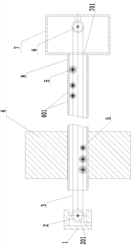
[0017] Such as figure 1 As shown, a device for dredging a landfill leachate drainage pipe according to the present invention includes a fixed frame 1, a traction rope 3 and a leachate drainage pipe 8; the leachate drainage pipe 8 is fixedly arranged on the dam body 4; the fixed frame 1 is arranged in the direction of one nozzle of the leachate drainage pipe 8; a fixed pulley is arranged in the direction of the other nozzle of the leachate drainage pipe 8 6; the inside of the fixed frame 1 is fixed with a hoist 2; the fixed frame 1 is arranged outside the dam body 4 for easy maintenance; the reel on the hoist 2 is a driving drum 201; one end of the traction rope 3 is connected to the On the driving drum 201; the other end of the traction rope 3 passes through the leachate drain pipe 8 and is connected to the fixed pulley 6; several steel wool balls 5 are fixed on the t...


PUM


Abstract

The invention relates to the technical field of environment geotechnical engineering, in particular to a refuse landfill leachate guide and drainage pipe dredging device. One end of a traction rope is connected onto an active roller; the other end of the traction rope passes through a leachate guide and drainage pipe to be connected onto the fixed pulley; a plurality of steel wire fuzzy balls are fixed on the traction rope. When the refuse landfill leachate guide and drainage pipe dredging device is used, a windlass starts, so that a steel wire fuzzy balls fixed on the traction rope can move to and fro in the leachate guide and drainage pipe; a pattern hole starts to be dredged; a residue structure remained in the leachate guide and drainage pipe is disordered, floats up, flows along with the leachate in the leachate guide and drainage pipe, and flows out to a discharging opening of the leachate guide and drainage pipe. The problems of blockage of the patterned hole of the refuse landfill leachate guide and drainage pipe and blockage of the leachate guide and drainage pipe are solved. The refuse landfill leachate guide and drainage pipe dredging device has the advantages that the structure is simple; safety and reliability are realized; the investment cost is low.

Description

technical field [0001] The invention relates to the technical field of environmental geotechnical engineering, in particular to a device for dredging a leachate guide and drainage pipe of a landfill site. Background technique [0002] With the rapid development of my country's economy and the improvement of urbanization level, the output of urban domestic waste has increased sharply, and the problems of waste disposal and pollution prevention have become increasingly prominent. Landfill is the main method for dealing with urban solid waste. [0003] Garbage landfills are mainly carried out in landfills. When the waste piles in the landfill degrade, landfill gas and a large amount of leachate will be produced. The leachate is collected at the bottom of the landfill by gravity. There is a leachate drainage pipe at the bottom of the landfill. The pipeline is a flower tube. The leachate flows into the pipe from the flower hole of the pipeline. A small slope is set, and the le...

Claims


Application Information

Patent Timeline
IPC IPC(8): E03F9/00
CPCE03F9/002
Inventor 唐睿曹丽厉江锋赵文阀李平吴兵兵金淑芳周向阳万晓葛芳
Owner SHENZHEN GAD ENVIRONMENTAL TECH
Learn More