Cone sleeve type grinding device for machining sealing ring with positive conical surface

A face sealing and grinding technology, used in seat surface grinders, metal processing equipment, grinding/polishing equipment, etc., can solve problems such as difficulty in effectively obtaining seal rings

Active Publication Date: 2017-07-14
XIHUA UNIV
View PDF4 Cites 0 Cited by
  • Summary
  • Abstract
  • Description
  • Claims
  • Application Information

AI Technical Summary

Problems solved by technology

[0003] Since the cone angle of the conical sealing surface on the sealing ring in the conical mechanical seal is small, the value is generally only a few minutes to tens of ten, so the maximum cutting amount of the end face in the axial direction during processing is only tens of microns, and Due to the very high requirements on the surface quality of the sealing end face, including surface roughness, flatness, perpendicularity to the axis, etc., it is difficult to obtain the sealing ring with a tapered sealing surface effectively by general methods.

Method used


Image

  • Cone sleeve type grinding device for machining sealing ring with positive conical surface
  • Cone sleeve type grinding device for machining sealing ring with positive conical surface
  • Cone sleeve type grinding device for machining sealing ring with positive conical surface

Examples


Embodiment Construction

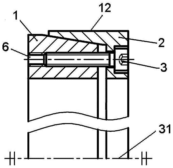
[0021] figure 1 Shown is the basic form of an overall structure of the tapered sleeve grinding device for processing positive tapered sealing rings according to the present invention, including an interpolation structure 1 and an outer sleeve structure 2 that can be mated with opposite ends in the axial direction. And can be mutually connected and fastened by connecting structures 3 arranged at equal intervals along the circumference. in:

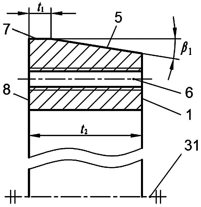
[0022] Such as figure 2 As shown, the interpolation structure 1 is an axial through-hole with a total axial length of t2 composed of an outer convex cone surface 5 with the central axis 31 as the center of rotation and a cylindrical peripheral surface segment 7 with an axial length of t1. For the cylindrical structure, the ratio of t1 to the total axial length t2 of the hole surface including the axial length of the convex cone surface 5 is t1 / t2=0.2. The radially outer side of the interpolation structure 1 is provided with 18 threaded ...


PUM


Abstract

The invention provides a cone sleeve type grinding device for machining a sealing ring with the positive conical surface. The cone sleeve type grinding device comprises an internal inserting structure and an external sleeving structure which can be matched in the axial direction in the mode that the opposite ends of the internal inserting structure and the external sleeving structure are held and inserted, wherein the internal inserting structure and the external sleeving structure can be connected and fastened with each other through a connecting structure. The holding and inserting matching portions of the internal inserting structure and the external sleeving structure take the central axes as the rotation centers correspondingly and are matching surfaces of the external convex conical table surface and the internal concave conical hole surface which are provided with conical angles correspondingly, and the conical angle of the rotation matching surface of the holding and inserting portion of the internal inserting structure is equal to or larger than that of the rotation matching surface of the holding and inserting portion of the external sleeving structure. The other end, opposite to the holding and inserting end, of the internal inserting structure is a standard end surface. The peripheral surface of the external sleeving structure takes the central axis as the rotation center as well and is provided with a cylindrical surface with the external diameter being suitable for the internal diameter of the machined sealing ring. According to the cone sleeve type grinding device, the sealing surface which only has several points to dozens of points, is dozens of microns in largest cutting quantity in the axial direction, has very a high surface quality demand over the sealing end face and is specially provided with the positive-cone-shaped surface can be conveniently and accurately machined on the sealing end face.

Description

technical field [0001] The invention relates to a grinding device for processing the sealing end face of a sealing ring, in particular to a sealing ring with a positive tapered sealing end face. Background technique [0002] The core components to achieve sealing in the mechanical seal are the moving ring which is axially fixed and can rotate with the shaft, and the non-rotating static ring which is arranged opposite to the moving ring through the sealing surface of the shaft end and can be used for axial floating. Cone mechanical seal refers to the sealing surface of the moving ring and / or static ring with a positive or reverse conical sealing surface with a certain taper in the radial direction and the end surface, and the adjustment is made by changing the parameters of the conical surface. The dynamic and static pressure effect of the fluid film formed by the medium between the sealing end faces to obtain sufficient opening force and fluid film rigidity. Cone mechanical...

Claims


Application Information

Patent Timeline
Patent Type & Authority Applications(China)
IPC IPC(8): B24B15/00
CPCB24B15/00
Inventor 王和顺朱维兵张均富杨伟
Owner XIHUA UNIV
Why Eureka
Try Eureka