Laser machining method based on EBL and application method thereof
A processing method and laser technology, applied in the field of lasers, can solve the problems of high cost and long processing time, and achieve the effects of reducing the total amount, improving production efficiency, and improving execution time
- Summary
- Abstract
- Description
- Claims
- Application Information
AI Technical Summary
Problems solved by technology
Method used
Image
Examples
Embodiment 1
[0067] Embodiment 1 of the present invention provides an EBL-based laser processing method. The processing method can be applied to a single laser or a laser array (the single laser and the array laser are collectively referred to as lasers hereinafter). This embodiment mainly proposes an alternative scheme of a sampling grating structure for the uniform grating structure adopted by a laser or an array laser that already exists. By adjusting the coupling coefficient, the laser made based on the sampling grating structure can obtain the same laser performance parameters as the laser products made of the existing uniform grating structure. Among them, the performance deviation of the two implementation methods can reach the industrial-grade parameter floating range Require. Such as figure 1 As described, the processing method proposed in the embodiment of the present invention includes the following execution steps:
[0068] In step 201, relevant parameters of the first reflec...
Embodiment 2
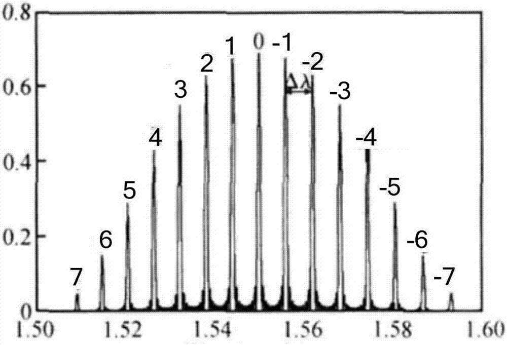
[0100] The embodiment of the present invention is based on Embodiment 1, and taking a specific three-layer structure sampling grating to replace the existing three-layer structure uniform grating as an example, and expounds how to obtain the minimum grating area length of the sampling grating. In this embodiment, the coupling coefficient of the 0th-order reflection peak of the sampling grating comb reflection spectrum formed by the sampling grating structure is K 0 =K*δ(3), such as image 3 As shown, where δ=Lg / Ls, Lg is the ratio result of the grating area length and the sampling length Ls, is the coupling coefficient of the existing uniform grating, where:
[0101]
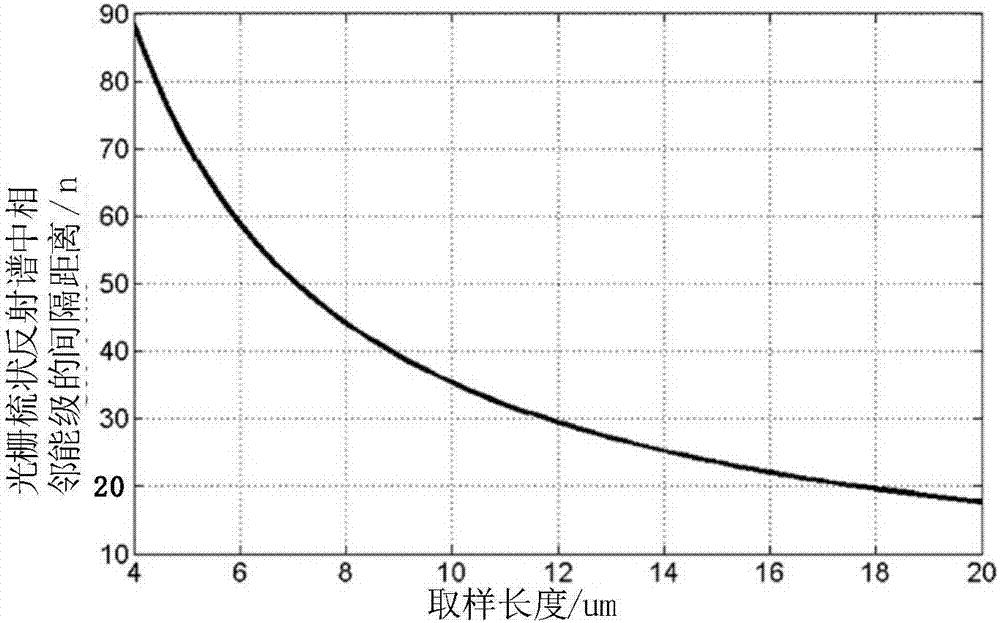
[0102] Such as Figure 5 with 5 As shown, N_core is the refractive index of the grating layer, a is the thickness of the existing uniform grating, G is the shape factor of the grating, λ is the working wavelength of the grating, n g is the effective refractive index (that is, the external refractive inde...
Embodiment 3
[0122] The above-mentioned embodiment 1 and embodiment 2 are mainly aimed at the existing uniform grating structure laser, how to design a sampling grating structure laser to replace the existing uniform grating structure laser, not only can ensure that the sampling grating structure laser and the existing uniform grating structure laser The parameter difference range is within the range of industrial requirements, and can effectively reduce the cost and processing efficiency problems during EBL system processing based on the calculated minimum grating area length of the sampling grating. The embodiment of the present invention starts from another perspective, that is, according to the relevant parameters of the laser to be produced, a laser with a sampling grating structure with low production cost and high production efficiency is designed. A kind of processing method of the laser based on EBL is provided in the embodiment of the present invention, such as Figure 9 As shown...
PUM
 Abstract
Description
Claims
Application Information
 - Generate Ideas
- Intellectual Property
- Life Sciences
- Materials
- Tech Scout
- Unparalleled Data Quality
- Higher Quality Content
- 60% Fewer Hallucinations
Browse by: Latest US Patents, China's latest patents, Technical Efficacy Thesaurus, Application Domain, Technology Topic, Popular Technical Reports.
© 2025 PatSnap. All rights reserved.Legal|Privacy policy|Modern Slavery Act Transparency Statement|Sitemap|About US| Contact US: help@patsnap.com


