
Power cable fault voltage traveling wave range finding method

A power cable and fault voltage technology, which is applied in the field of power cable fault voltage traveling wave distance measurement, can solve the problem that the reflected pulse at the fault point and the ball gap pulse are not easy to distinguish, and achieve the effects of easier analysis and identification, improved efficiency, and low cost

Inactive Publication Date: 2017-07-07
淄博威特电气有限公司
View PDF6 Cites 6 Cited by
  • Summary
  • Abstract
  • Description
  • Claims
  • Application Information

AI Technical Summary

Problems solved by technology

Due to the fact that the reflected pulse at the fault point and the ball gap pulse have the same polarity, it is difficult to distinguish between the reflected pulse at the fault point and the ball gap pulse

Method used


Image

  • Power cable fault voltage traveling wave range finding method
  • Power cable fault voltage traveling wave range finding method

Examples


Embodiment Construction

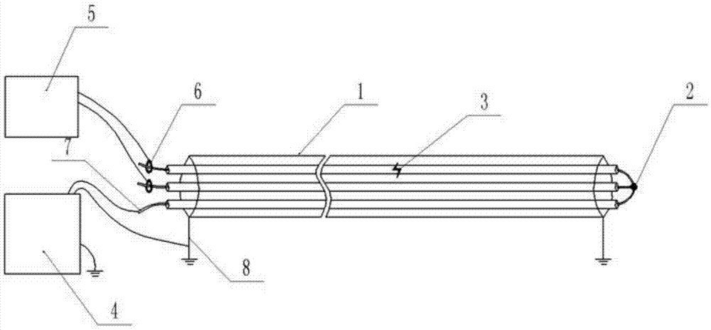
[0019] Such as figure 1 As shown, a voltage sensor is installed on the faulty phase and the intact phase of the power cable under test, and the other end of the power cable is short-circuited at the same time for three phases;

[0020] The two-way voltage sensors are respectively connected to the two-way high-speed sampling units of the cable fault tester to form a double-way synchronous sampling structure.

[0021] Apply a high-voltage pulse signal to another intact phase that is not connected to the voltage sensor to cause the fault point to discharge and breakdown;

[0022] Through the dual-channel high-speed sampling unit and voltage sensor in the cable fault distance meter, the voltage traveling wave data of the fault phase and the intact phase are recorded at the same time;

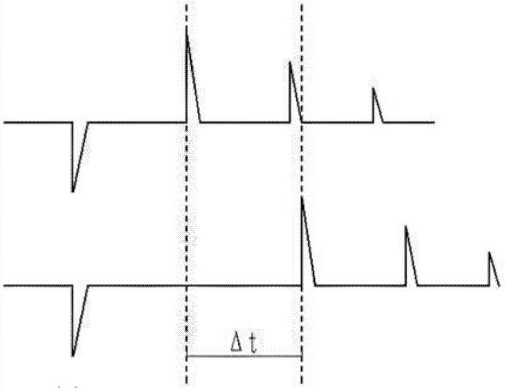
[0023] Analyze the voltage traveling wave data collected in step 4. According to the characteristics of the voltage traveling wave discharge at the fault point, the time difference Δt between the f...


PUM


Abstract

The invention belongs to the electric power system monitoring field and especially relates to a power cable fault voltage traveling wave range finding method. The method is characterized by carrying out opposite end loop on a detected circuit; applying a high-voltage pulse signal to a sound phase of a detected power cable; simultaneously, recording voltage traveling wave reflection waveforms of a fault phase and another sound phase; and using a time difference of first wave peaks or wave troughs of traveling wave data of the fault phase and the sound phase to analyze and calculate a fault distance. By using the method, high accuracy is possessed; polarities of a fault point reflection pulse and a sphere gap pulse are opposite so that the fault point reflection pulse and the sphere gap pulse are easy to distinguish; and simultaneously, in a voltage traveling wave method, a high voltage capacitor does not need to be added and there is little increase in cost.

Description

[0001] Technical field: [0002] The invention belongs to the field of power system monitoring, and in particular relates to a method for measuring the distance of a power cable fault voltage traveling wave. [0003] Background technique: [0004] At present, the pulse current method is generally used in the fault location of the line. This method is to measure the current traveling wave data of the fault phase by applying a high-voltage pulse signal to the fault phase of the fault cable to make the fault point discharge. Due to the fact that the reflected pulse at the fault point and the ball gap pulse have the same polarity, it is difficult to distinguish between the reflected pulse at the fault point and the ball gap pulse. [0005] Invention content: [0006] The purpose of the present invention is to overcome the deficiencies of the prior art and provide a simple, convenient and accurate power cable fault voltage traveling wave ranging method that can overcome the above-m...

Claims


Application Information

Patent Timeline
IPC IPC(8): G01R31/11
CPCG01R31/11G01R31/083
Inventor 李义明陈宗军李桂义
Owner 淄博威特电气有限公司
Learn More