
Dehumidification device and control method thereof

A technology for controlling valves and pipelines, which is applied in control input related to air characteristics, heating and ventilation control system, space heating and ventilation control input, etc. question

Active Publication Date: 2017-07-07
BEIJING JINMAO GREEN BUILDING TECH CO LTD
View PDF5 Cites 2 Cited by
  • Summary
  • Abstract
  • Description
  • Claims
  • Application Information

AI Technical Summary

Problems solved by technology

The traditional basement dehumidification adopts natural ventilation, but natural ventilation is greatly affected by the outdoor climate. Summer ventilation causes the basement to be humid and hot, and winter ventilation causes the basement to be cold.
In order to solve this problem, the air conditioner in the basement can be turned on, but the load of the underground building is very small, and turning on the air conditioner will cause energy waste virtually.
[0005] In recent years, the temperature independent control air conditioning technology is also developing rapidly, with high comfort, high efficiency and energy saving radiant air conditioning system as a typical representative, but it needs to be equipped with special dehumidification equipment, which cannot achieve high efficiency and energy saving
A bottleneck affecting the development of this system is that there is no dehumidification equipment with good performance and high efficiency and energy saving
[0006] At present, most of the dehumidification equipment on the market use indoor circulating air, which cannot solve the problem of indoor ventilation when solving the dehumidification problem. The dehumidification equipment that can be connected to fresh air has the problem that the dehumidification depth cannot meet the requirements, or the condensation heat of the compressor cannot be discharged during dehumidification.

Method used


Image

  • Dehumidification device and control method thereof
  • Dehumidification device and control method thereof
  • Dehumidification device and control method thereof

Examples


Embodiment Construction

[0057] The specific embodiments of the present invention will be further described below in conjunction with the drawings. The same parts are indicated by the same reference numerals. It should be noted that the words "front", "rear", "left", "right", "upper" and "lower" used in the following description refer to the directions in the drawings, and the words "inner" and "outer" "Respectively refers to the direction toward or away from the geometric center of a particular component.

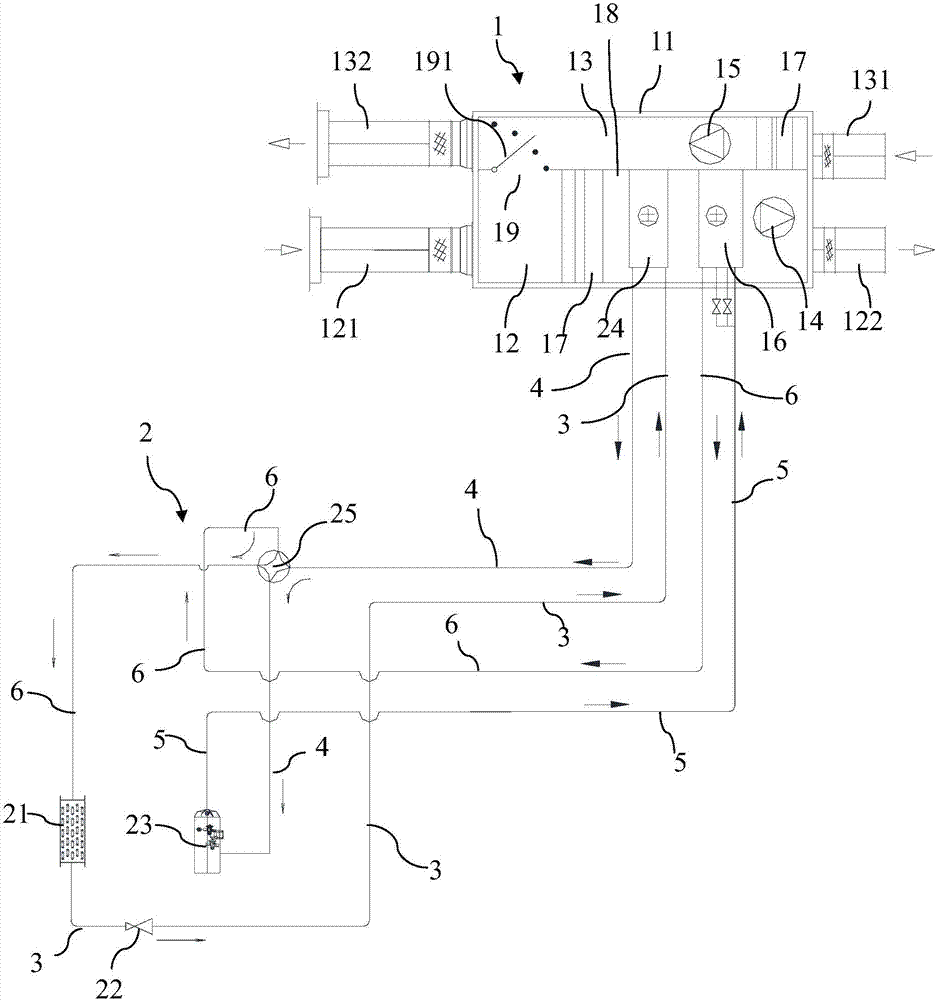
[0058] Such as figure 1 As shown, a dehumidification device provided by an embodiment of the present invention includes a fan assembly 1 and a host 2.

[0059] The fan assembly 1 includes a housing 11 having an air inlet channel 12, and the housing 11 is also provided with an air inlet 121 and an air outlet 122 communicating with the air inlet channel 12. A blower 14 for blowing air to the side of the air outlet 122 is provided in the air inlet channel 12.

[0060] The host 2 includes a main condenser...


PUM


Abstract

The invention discloses a dehumidification device which comprises a fan assembly and a host. The fan assembly comprises a shell with an air inlet channel. An air inlet and an air outlet are further formed in the shell. An air supply fan is arranged in the air inlet channel. The host comprises a main condenser, an expansion valve, a compressor and an evaporator. The evaporator is arranged in the air inlet channel, and a heater is further arranged in the air inlet channel. An outlet of the main condenser and an inlet of the evaporator are connected through a first pipeline. An outlet of the evaporator and an inlet of the compressor are connected through a second pipeline. An outlet of the compressor and an inlet of the heater are connected through a third pipeline. An outlet of the heater and an inlet of the main condenser are connected through a fourth pipeline. The invention further discloses a control method of the dehumidification device. According to the dehumidification device and the control method thereof, condensation waste heat is fully utilized in the whole dehumidification and heating process, no extra load is needed, and the effects of high efficiency and energy saving are achieved.

Description

Technical field [0001] The invention relates to the technical field of air dehumidification, in particular to a dehumidification device and a control method thereof. Background technique [0002] In South China and East China (such as Haikou, Chongqing, Chengdu, Guangzhou, etc.), the average temperature in summer is 30-35℃, humidity is 70-90%, the temperature is high and the humidity is high, and the average temperature in winter is 10-20℃, and the humidity is 80-90%. The temperature is low and the humidity is very high, and the human body comfort is poor, especially in the "Hui Nantian" and "meiyu days", the air humidity is close to saturation, this area needs to be dehumidified all the year round, while dehumidification must also solve the indoor ventilation problem. [0003] In North China, the summer is hot and humid and the winter is dry and cold, and the summer requires dehumidification and heating in winter to solve the problem of indoor fresh air ventilation. The tradition...

Claims


Application Information

Patent Timeline
Patent Type & Authority Applications(China)
IPC IPC(8): F24F3/14F24F13/28F24F11/02F24F11/00
CPCF24F3/14F24F11/30F24F11/89F24F13/28F24F2110/00Y02B30/70
Inventor 武振兴李俊左建波王福乔杨冰
Owner BEIJING JINMAO GREEN BUILDING TECH CO LTD
Learn More