
Lock bolt component

A technology for preventing loosening of bolts and bolts, applied in the direction of bolts, threaded fasteners, screws, etc., can solve the problem of easily damaged connecting parts or connected parts, and the torsion of stop pads is small and good, but it is necessary to drill holes on the bolts. The specific position of the bolt needs to be preset in advance, so as to achieve the effect of good anti-loosening effect and mature and reliable technology.

Inactive Publication Date: 2017-07-07
王大俊
View PDF5 Cites 5 Cited by
  • Summary
  • Abstract
  • Description
  • Claims
  • Application Information

AI Technical Summary

Problems solved by technology

In the prior art, the commonly used anti-loosening methods are as follows: one is to use a spring washer with a flat washer and an oblique opening close to the head of the nut, and use the elastic deformation of the spring washer to tension the threaded counter axially. , and use the resistance of the oblique opening of the gasket to prevent loosening, but in the high-frequency, severe, and long-term vibration of the vibrating equipment, the anti-loosening effect is not ideal; the second is to adopt a permanent anti-loosening method, that is, welding, punching The other method is to eliminate the relative transfer of the thread pair. Although this method is reliable in preventing loosening, it is easy to damage the connecting parts or the connected parts when it needs to be disassembled; the third is to use cotter pins. Drilling on the top, the specific position of the bolt needs to be preset in advance, so it cannot be widely used; the fourth is to use a stop pad, but the torque of the stop pad to withstand loosening is small

Method used


Image

  • Lock bolt component
  • Lock bolt component
  • Lock bolt component

Examples


Embodiment Construction

[0020] The present invention will be described in further detail below in conjunction with the accompanying drawings.

[0021] The first embodiment of the present invention

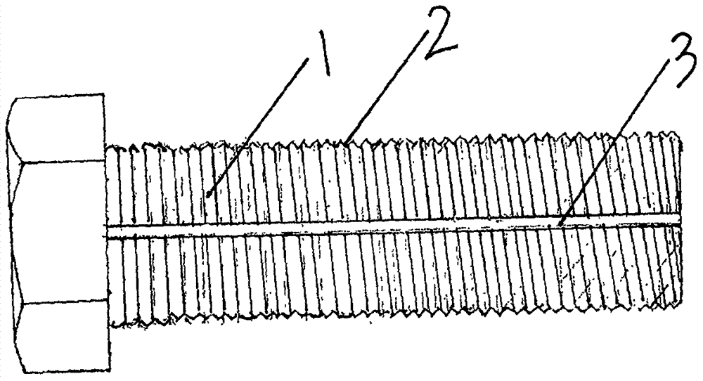
[0022] refer to figure 1 , figure 2 , image 3 . exist figure 1 Among them, 1 is the bolt in the anti-loosening bolt assembly, and the thread 2 is on the bolt. A stop groove 3 is arranged on the top of the bolt 1 . The number of the stop grooves 3 can also be set to two, three or more as required. The length of the stop groove 3 can be set to be 1 / 2 of the bolt length, 1 / 3 of the bolt length, etc. in addition to being set to be equal to the bolt length.

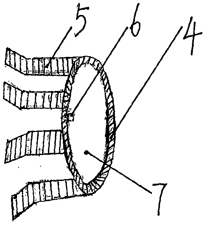
[0023] exist figure 2 Among them, the ring piece 4, the pressing piece 5, the stop protrusion 6, and the bolt channel hole 7 jointly form the stop snap ring sleeve. A compression piece 5 that can produce elastic deformation is fixed on the ring piece 4 of the stop snap ring sleeve, for example: a steel sheet with better elasticity can be used ...


PUM


Abstract

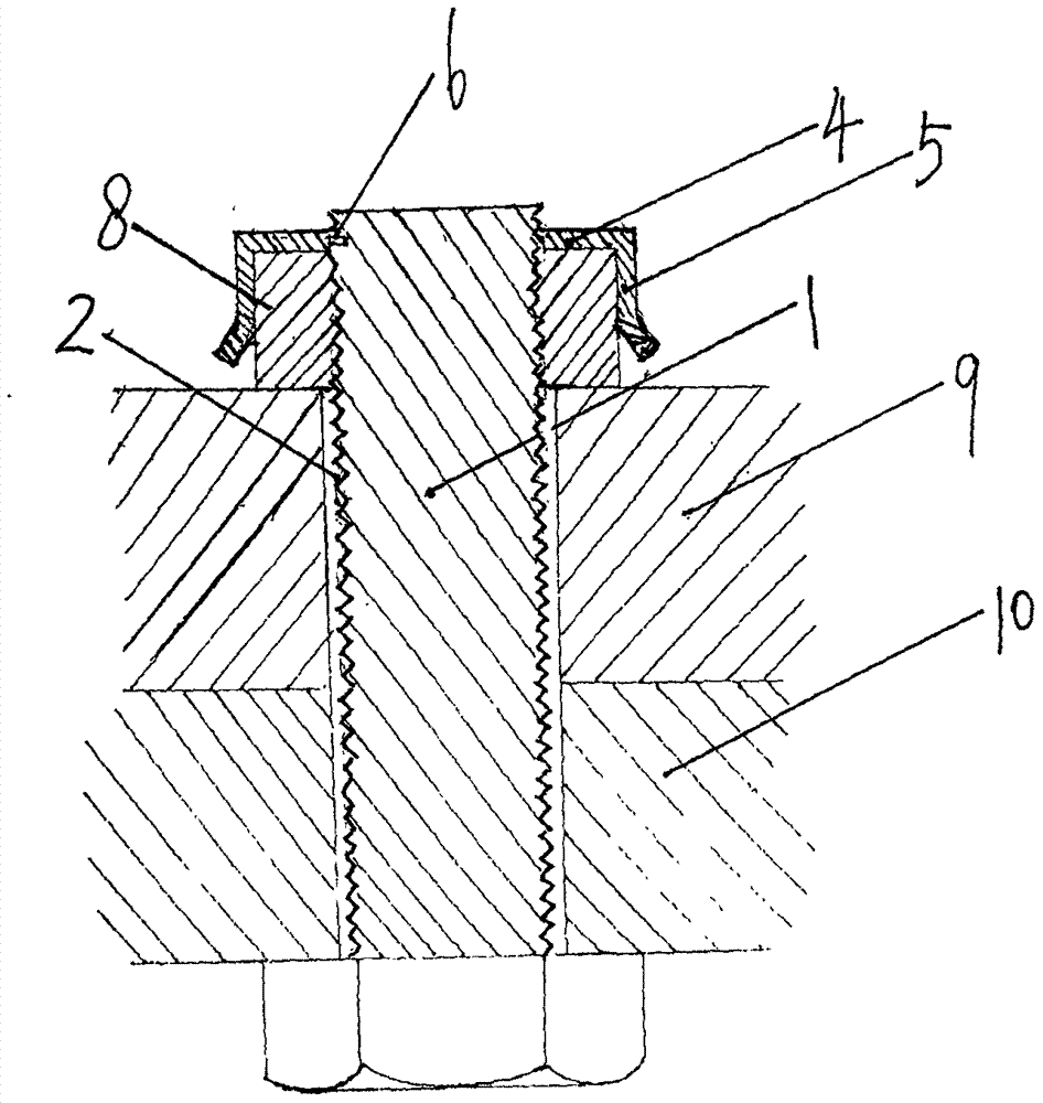
The invention discloses an anti-loosening bolt assembly, which can effectively prevent nuts from loosening and can be disassembled. It consists of a bolt (1), a nut (8), and a stop snap ring sleeve, and is characterized in that: a stop groove (3) is arranged in the axial direction of the bolt (1); the stop snap ring sleeve is composed of ring pieces (4 ), a compression piece (5), a stop protrusion (6), and a bolt passage hole (7), and a compression piece (5) capable of producing elastic deformation is fixed on the ring piece (4) of the stop snap ring sleeve , the ring piece (4) is provided with a bolt channel hole (7), on the radial inner edge of the ring piece (4) is provided with a stop protrusion (6) corresponding to the stop groove (3), the stop card The ring sleeve passes through the bolt (1) through the bolt channel hole (7) so that the stop protrusion (6) enters the stop groove (3) of the bolt (1), and presses the pressing piece (5) to the nut (8) up. Figure 3 is the accompanying drawing of the abstract of the description.

Description

technical field [0001] The invention relates to a bolt assembly, in particular to an anti-loosening bolt assembly. Background technique [0002] In order to prevent loosening of connecting fasteners during vibration and impact, an anti-loosening device is required for anti-loosening. In the prior art, the commonly used anti-loosening methods are as follows: one is to use a spring washer with a flat washer and an oblique opening close to the head of the nut, and use the elastic deformation of the spring washer to tension the threaded counter axially. , and use the resistance of the oblique opening of the gasket to prevent loosening, but in the high-frequency, severe, and long-term vibration of the vibrating equipment, the anti-loosening effect is not ideal; the second is to adopt a permanent anti-loosening method, that is, welding, punching The other method is to eliminate the relative transfer of the thread pair. Although this method is reliable in preventing loosening, it ...

Claims


Application Information

Patent Timeline
Patent Type & Authority Applications(China)
IPC IPC(8): F16B39/10F16B39/04
CPCF16B39/103F16B39/04F16B39/106
Inventor 王大俊
Owner 王大俊
Learn More