Eureka AIR delivers breakthrough ideas for toughest innovation challenges, trusted by R&D personnel around the world.

Lock nut and using method

A technology of anti-loosening nuts and internal nuts, which is applied in the direction of nuts, screws, bolts, etc., can solve the problems of difficult installation, difficult processing, equipment failure, etc., and achieve the effect of small occupied area, good anti-loosening effect and convenient installation

Active Publication Date: 2015-11-11
钟跃荣
View PDF10 Cites 4 Cited by
  • Summary
  • Abstract
  • Description
  • Claims
  • Application Information

AI Technical Summary

Problems solved by technology

However, in the case of strong vibration or irregular force, the bolts and nuts will loosen, which will lead to serious accidents such as equipment failure and even casualties. For this reason, there have been many locknuts and lockbolts. invention
[0003] CN103195786A discloses a kind of anti-loosening nut that can prevent self-loosening on the bolt. Through the assembly of the main nut and the auxiliary nut, the anti-loosening is realized. When it is too large, the auxiliary nut will be tightly locked with the bolt to become one, so that it cannot be prevented from loosening;
[0004] CN104074854A discloses a kind of anti-loosening nut, and anti-loosening is realized by inserting bayonet pins on the side of the nut, but since the bayonet pins have no pre-tightening force, the bayonet pins will only play a role when the nut is loosened to the stop position. Therefore, this method is actually not to prevent loosening but to avoid falling off;
[0005] CN102606606A discloses an anti-loosening bolt. The anti-loosening is realized by double-locking the bolt with the reversed nut and the standard nut. This method uses the friction force between the reversed nut and the standard nut to prevent the bolt from loosening. When the shear force is greater than the friction force, the bolt will still drive the anti-clamp nut to move and cannot be loosened, and the bolts used in this method must be customized, non-standard parts, and cannot be used universally;
[0006] CN104405752A discloses a kind of anti-loosening bolt, through the combination of the inner screw cone and the outer nut, the anti-loosening of the internal and external threads is adopted to achieve anti-loosening; but the inner nut used in this method is conical, and the conical nut is processed The requirements are very high, the processing is difficult, and it is relatively difficult to produce, and the anti-loosening bolt described in CN104405752A has a complicated structure and is difficult to install
[0007] At present, the tightening of bolts and nuts on the market is usually achieved by the friction between the bottom surface of the nut and the bottom surface of the bolt head. The required tightening force is relatively large and laborious.

Method used


Image

  • Lock nut and using method
  • Lock nut and using method
  • Lock nut and using method

Examples


Embodiment 1

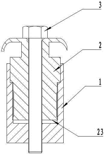
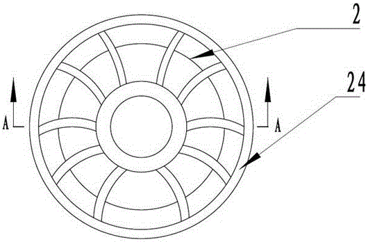
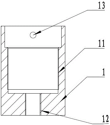
[0034] As shown in the accompanying drawings: a lock nut, including an outer nut 1 and an inner nut 2, the inner nut 2 is provided with a first internal thread 21, the lower end of the outer wall of the inner nut 2 is provided with an outer thread 22; There is a second internal thread 11 , and a third internal thread 12 is provided at the inner bottom of the outer nut 1 ; the inner nut 2 is installed in the outer nut 1 .

[0035] The direction of rotation of the external thread 1 is consistent with that of the second internal thread 11, and the direction of rotation of the external thread 22 is opposite to that of the first internal thread 21 and the third internal thread 12; The internal thread 11 is connected, and the bolt 4 is connected with the first internal thread 21 of the internal nut 2 and the third internal thread 12 of the external nut 1 .

[0036] Preferably, in this embodiment, the distance between the first plane 23 at the bottom of the inner nut 2 and the second...

Embodiment 2

[0045] Embodiment 2 is generally consistent with the implementation of Embodiment 1, the difference is that in Embodiment 2, the distance between the first plane 23 at the bottom of the inner nut 2 and the second plane 13 below the second internal thread 11 in the outer nut 1 is 2 times the pitch, the engagement length of the external thread 22 and the second internal thread 11 is 1.5 times the thread length of the third internal thread 12 .

[0046] Through the embodiments, it can be found that the present invention has the following characteristics compared with the prior art: 1. The present invention engages the forward and reverse threads after the bolts are tightened by hand, so that the bolts cannot be loosened, and the anti-loosening effect is good; 2. The structure is simple, and the Simple tightening of nuts and bolts can achieve anti-loosening; 3. Easy installation, the invention can be installed immediately after use, occupies a small area, and can be adapted accordi...


PUM


Abstract

A lock nut comprises an outer nut and an inner nut. A first internal thread is formed inside the inner nut. An external thread is formed in the lower end of the outer wall of the inner nut. A second internal thread is formed in the middle inside the outer nut. A third internal thread is formed in the bottom end inside the outer nut. The inner nut is installed inside the outer nut. The external thread and the second internal thread are consistent in screwing direction. The external thread and the first internal thread are opposite in screwing direction. The external thread and the third internal thread are opposite in screwing direction. The distance between a first plane at the bottom of the inner nut and a second plane below the second internal thread inside the outer nut is not smaller than the one-fold screw pitch. The lock nut has the beneficial effects that a bolt cannot loosen after the bolt is screwed down by hand and the left-hand and right-hand threads are meshed, and the anti-looseness effect is good; the structure is simple, looseness prevention can be achieved by easy nut and bolt fastening; installation is convenient; the optional bolt range is wide; when the bolt is screwed down, the bottom face of the head of the bolt and the top face of the inner nut are not in contact, and therefore the needed pretightening force is much smaller than that in the prior art.

Description

technical field [0001] The invention relates to a nut, in particular to a lock nut and a usage method. Background technique [0002] As the most commonly used detachable fastening parts, bolts and nuts are widely used in various fields of society. However, in the case of strong vibration or irregular force, the bolts and nuts will loosen, which will lead to serious accidents such as equipment failure and even casualties. For this reason, there have been many locknuts and lockbolts. invention. [0003] CN103195786A discloses a kind of anti-loosening nut that can prevent self-loosening on the bolt. Through the assembly of the main nut and the auxiliary nut, the anti-loosening is realized. When it is too large, the auxiliary nut will be tightly locked with the bolt to become one, so that it cannot be prevented from loosening; [0004] CN104074854A discloses a kind of anti-loosening nut, and anti-loosening is realized by inserting bayonet pins on the side of the nut, but sinc...

Claims


Application Information

Patent Timeline
Patent Type & Authority Applications(China)
IPC IPC(8): F16B39/12F16B41/00F16B37/00
CPCF16B37/00F16B39/12F16B41/00
Inventor 钟跃荣
Owner 钟跃荣
Why Eureka
Eureka Blog
Learn More